
Windshield wiper blade structure

a technology of wiper blades and windshields, which is applied in the field of windshield wiper blade structures, can solve the problems of increased manufacturing costs and inconvenient cleaning, and achieve the effect of reducing maintenance and repair costs and easy removal of damaged or aging wiper strips

Inactive Publication Date: 2010-09-30
UNIPOINT ELECTRIC MANUFACTURING CO LTD
View PDF10 Cites 89 Cited by
  • Summary
  • Abstract
  • Description
  • Claims
  • Application Information

AI Technical Summary

Benefits of technology

[0005]It is therefore a primary object of the present invention to provide a windshield wiper blade structure that allows a user to easily replace a wiper strip thereof with a new one, so as to overcome the problem of requiring high cost to replace a whole set of windshield wiper blade when a wiper strip thereof is aged or damaged, as found in the prior art.
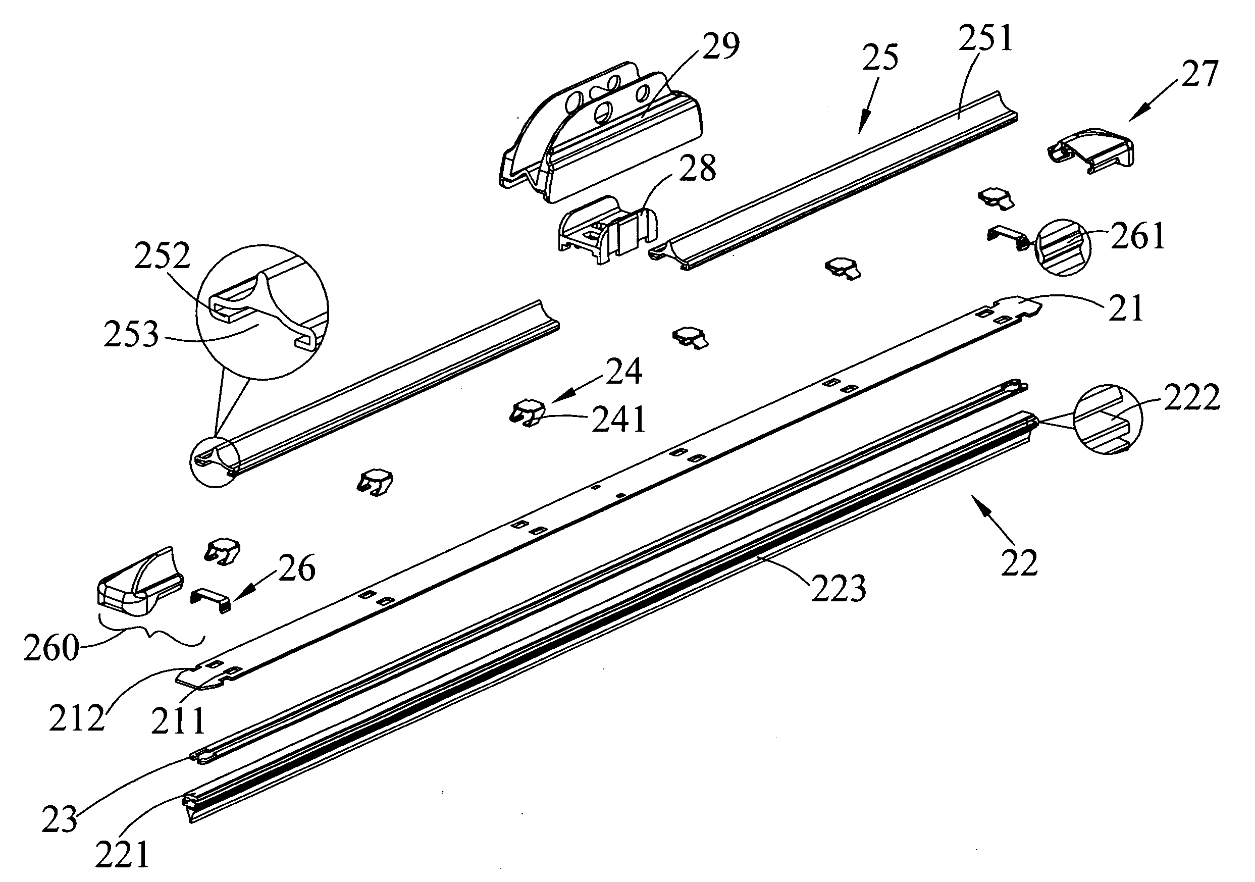
[0012]With the above arrangements, the end caps can be connected to or removed from two longitudinally opposite ends of the support strip simply by compressing the two elastic arms on each of the elastic locking elements toward each other and then releasing the two elastic arms, enabling a user to easily remove the damaged or aged wiper strip from the support strip for replacement without the need of discarding a whole set of the windshield wiper blade structure. Therefore, the maintenance and repair cost can be reduced.

Problems solved by technology

This is of course not economical to do so.
Thus, the conventional windshield wiper blade structure is manufactured at increased cost.

Method used


Image

  • Windshield wiper blade structure
  • Windshield wiper blade structure
  • Windshield wiper blade structure

Examples


Embodiment Construction

[0027]The present invention will now be described with some preferred embodiments thereof with reference to the accompanying drawings.

[0028]Please refer to FIG. 3 that is an exploded perspective view of a windshield wiper blade structure according to a first embodiment of the present invention, and to FIG. 4 that is an enlarged assembled cross-sectional view of the windshield wiper blade structure of FIG. 3. As shown, the windshield wiper blade structure in the first embodiment includes a support strip 21, a wiper strip 22, two flexible strips 23, a plurality of clamping elements 24, two wind deflector strips 25, a binding component 260, a bracket 28, and a protective cover 29. The binding component 260 includes two elastic locking elements 26 and two end caps 27.

[0029]The support strip 21 is formed with a plurality of pairs of holes 211 and two notched sections 212. The pairs of holes 211 are axially equally spaced along the support strip 21 and the holes in each of the pairs are a...


PUM


Abstract

A windshield wiper blade structure includes a support strip, a wiper strip disposed below the support strip, two flexible strips set on two sides of the wiper strip, a set of clamping elements downward extended through holes formed on the support strip to clamp the support strip, the flexible strips and the wiper strip together, two wind deflector strips disposed on a top of the support strip, two elastic locking elements each including two elastic arms separately fitted near two opposite ends of the support strip, and two end caps detachably connected to the two ends of the support strip and each internally provided with two notches engaged with the elastic arms. By compressing the elastic arms toward each other to disengage them from the notches, the end caps can be removed from the support strip to allow replacement of the wiper strip with a new one.

Description

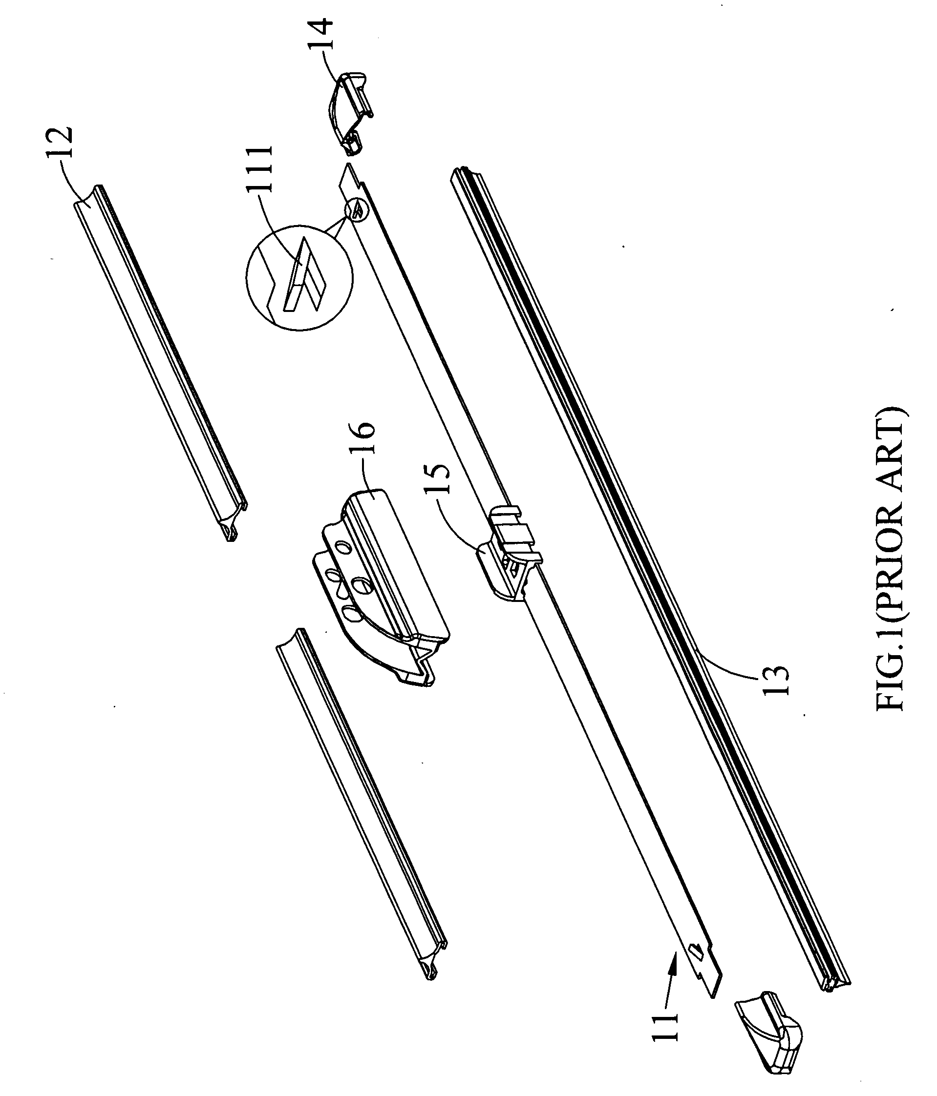
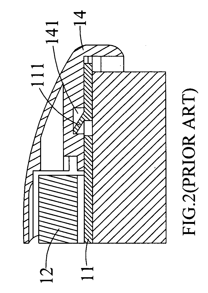
FIELD OF THE INVENTION[0001]The present invention relates to a windshield wiper blade structure, and more particularly to a windshield wiper blade structure that allows a user to easily replace a wiper strip thereof with a new one.BACKGROUND OF THE INVENTION[0002]A windshield wiper structure is usually installed close to a windshield of a motor vehicle, and a wiper blade thereof is driven to swing back and forth within a generally sector-shaped wiping area. The wiper blade has a wiper strip made of a rubber material for wiping off deposited dust or water, such as wiping accumulated rainwater or snow from the windshield.[0003]FIG. 1 is an exploded perspective view of a conventional windshield wiper blade structure; and FIG. 2 is a fragmentary, enlarged and assembled sectional view of the conventional windshield wiper blade structure of FIG. 1. As shown, the conventional windshield wiper blade structure includes a support strip 11, two wind deflector strips 12 disposed on a top of the...

Claims


Application Information

Patent Timeline
IPC IPC(8): B60S1/32
CPCB60S1/381B60S2001/382B60S1/3891B60S1/3881
Inventor CHIEN, CHING CHUAN
Owner UNIPOINT ELECTRIC MANUFACTURING CO LTD
Learn More