Construction machine

Active Publication Date: 2010-09-30
HITACHI CONSTR MASCH CO LTD
View PDF17 Cites 2 Cited by
  • Summary
  • Abstract
  • Description
  • Claims
  • Application Information

AI Technical Summary

Benefits of technology

[0018]By thus jointing the intermediate plate member and the reinforcing member by the fillet welding, it is possible to strongly joint the intermediate plate member and the reinforcing member. In addi

Problems solved by technology

However, in a case where the door body press-formed in the three-dimensional curved surface configuration by using the press die and the reinforcing member formed by the bending process as described above are abutted against each other, a slight gap is to be generated therebetween due to

Method used


Image

  • Construction machine
  • Construction machine
  • Construction machine

Examples


Example

[0029]1: Hydraulic excavator (construction machine)[0030]2: Lower traveling structure (vehicle body)[0031]3: Upper revolving structure (vehicle body)[0032]7: Engine (onboard equipment)[0033]8: Heat exchanger (onboard equipment)[0034]9: Hydraulic pump (onboard equipment)[0035]11: Fuel tank (member of a vehicle body side)[0036]14: Housing cover[0037]18: Right side door (door)[0038]19, 28: Door body[0039]19A: Inner side surface[0040]22: Intermediate plate member[0041]23: Spot welding portion[0042]24: Reinforcing member[0043]25: Fillet welding portion[0044]26: Hinge[0045]27: Left side door (door)

BEST MODE FOR CARRYING OUT THE INVENTION

[0046]Hereinafter, a case where an embodiment of a construction machine according to the present invention is applied to a hydraulic excavator will be taken as an example, which will be explained with reference to the accompanying drawings.

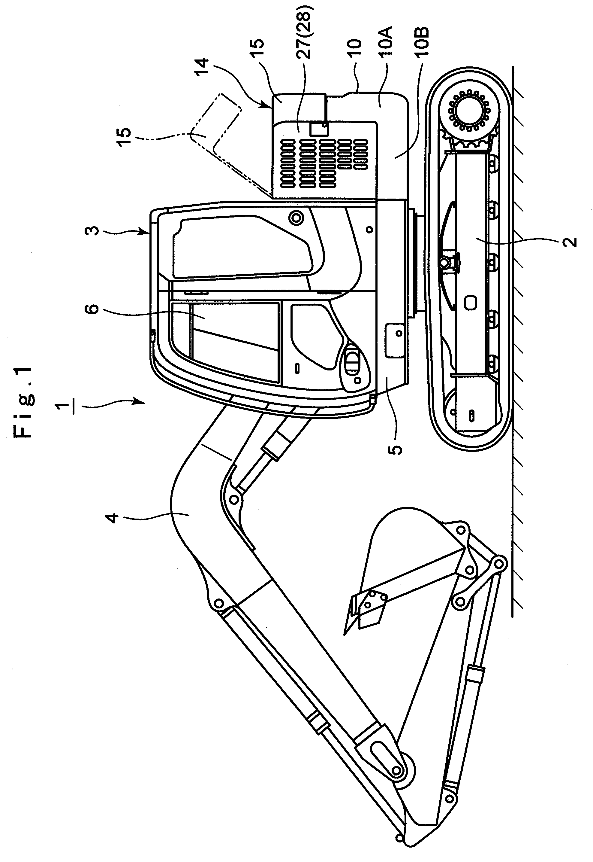
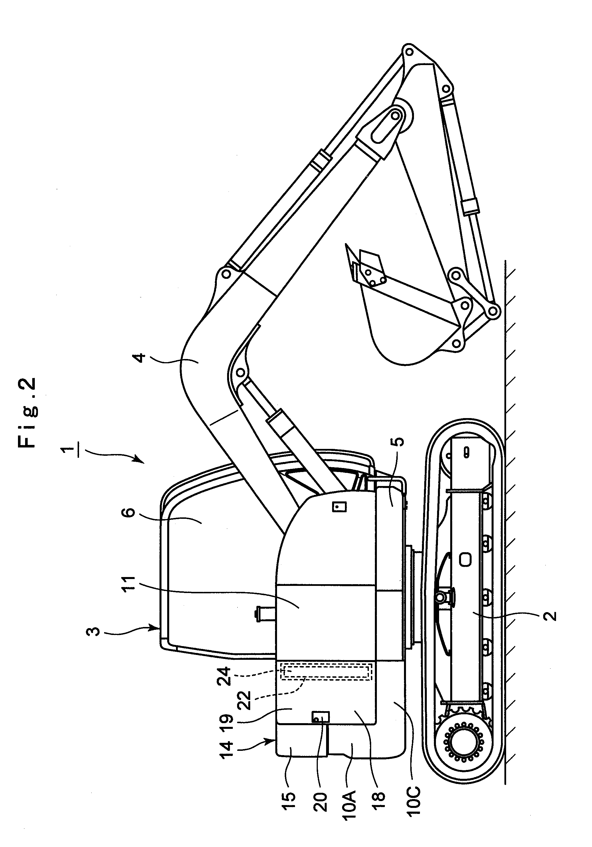
[0047]In the drawings, denoted at 1 is a hydraulic excavator as a representative example of a construction machine. A ...


PUM


Abstract

An intermediate plate member (22) having a plate thickness equal to or less than that of a door body (19) is provided between the door body (19) and a reinforcing member (24) constituting a right side door (18). The door body (19) and the intermediate plate member (22) are jointed by spot welding, and the intermediate plate member (22) and the reinforcing member (24) are jointed by fillet welding, thereby jointing the reinforcing member (24) through the intermediate plate member (22) on the inner side surface (19A) of the door body (19). Through the use of the intermediate plate member (22), the generation of distortion in the door body (19) is reduced and the outer appearance of the right side door (18) is maintained in good condition.

Description

TECHNICAL FIELD[0001]The present invention relates to a construction machine such as a hydraulic excavator or hydraulic crane, and particularly to a construction machine equipped with an openable and closable door constituting a part of a housing cover.BACKGROUND ART[0002]A hydraulic excavator as a representative example of a construction machine generally comprises an automotive lower traveling structure, an upper revolving structure swingably mounted on the lower traveling structure, and a working mechanism mounted liftably in a front side of the upper revolving structure, and a ground excavating operation is performed by lifting up and down the working mechanism.[0003]The upper revolving structure is configured mainly by a revolving frame as a base, a cab defining an operation room located at a left front portion of the revolving frame, a counterweight located in a rear end portion of the revolving frame to serve as a weight balance to the working mechanism, and a housing cover l...

Claims


Application Information

Patent Timeline
IPC IPC(8): E02F9/00
CPCB62D25/12B66C23/62E02F9/0891E02F9/0816E02F9/00
Inventor OKADA, KAZUMASANAKAMURA, MASAOMATSUSHITA, MAKOTO
Owner HITACHI CONSTR MASCH CO LTD
Why Eureka
Try Eureka