Micromixer biochip

a micro-mixer and biochip technology, applied in the direction of mixing, transportation and packaging, chemistry apparatus and processes, etc., can solve the problems of consuming a great amount of substances, consuming a great amount of time, and the mixing technique is not favorable to biochemical applications

Active Publication Date: 2010-09-30
NAT CHENG KUNG UNIV
View PDF5 Cites 0 Cited by
  • Summary
  • Abstract
  • Description
  • Claims
  • Application Information

AI Technical Summary

Benefits of technology

[0007]In view of the drawbacks of conventional micromixers, it is an objective of the present invention to provide a micromixer biochip that mixes substances with active vortex flows. Therefore, drawbacks of a conventional micromixer utilizing passive mixing methods, such as poor mixing performance or requiring large volume samples, can be overcome.
[0010]During the operation of the micromixer biochip of the present invention, the top portion of the single-opening fluidic channel can be induced up-and-down deformations by frequently controlling the pressure inside the air chambers. Such up-and-down deformations of the top portion of the single-opening fluidic channel can introduce the fluid from the single-opening fluidic channel to the mixing chamber, and vice versa. In addition, since the axis of the single-opening fluidic channels does not pass through the center of the mixing chamber, the moving fluids can generate a vortex flow in the mixing chamber and accomplish the mixing effect.

Problems solved by technology

Thus, to develop micromixers that are simple in design yet can achieve effective mixing within a short time has been an important issue for biochip researchers.
This kind of mixing technique is not favorable for biochemical applications, since the mixing performance is generally poor and it consumes much time for substances to be completely mixed.
However, conventional micromixers generally consume great volume and tend to use large measuring cups, magnetic bars or magnetic rotational devices.
As such, mixing substances placed in such large container through the rotation of the magnetic bars will consume a great amount of substances and much more time, and the product produced may demonstrate an uneven temperature distribution.

Method used


Image

  • Micromixer biochip
  • Micromixer biochip
  • Micromixer biochip

Examples


example 1

Mixing Efficiency of a Micromixer Biochip Including Four Single-Opening Fluidic Channels

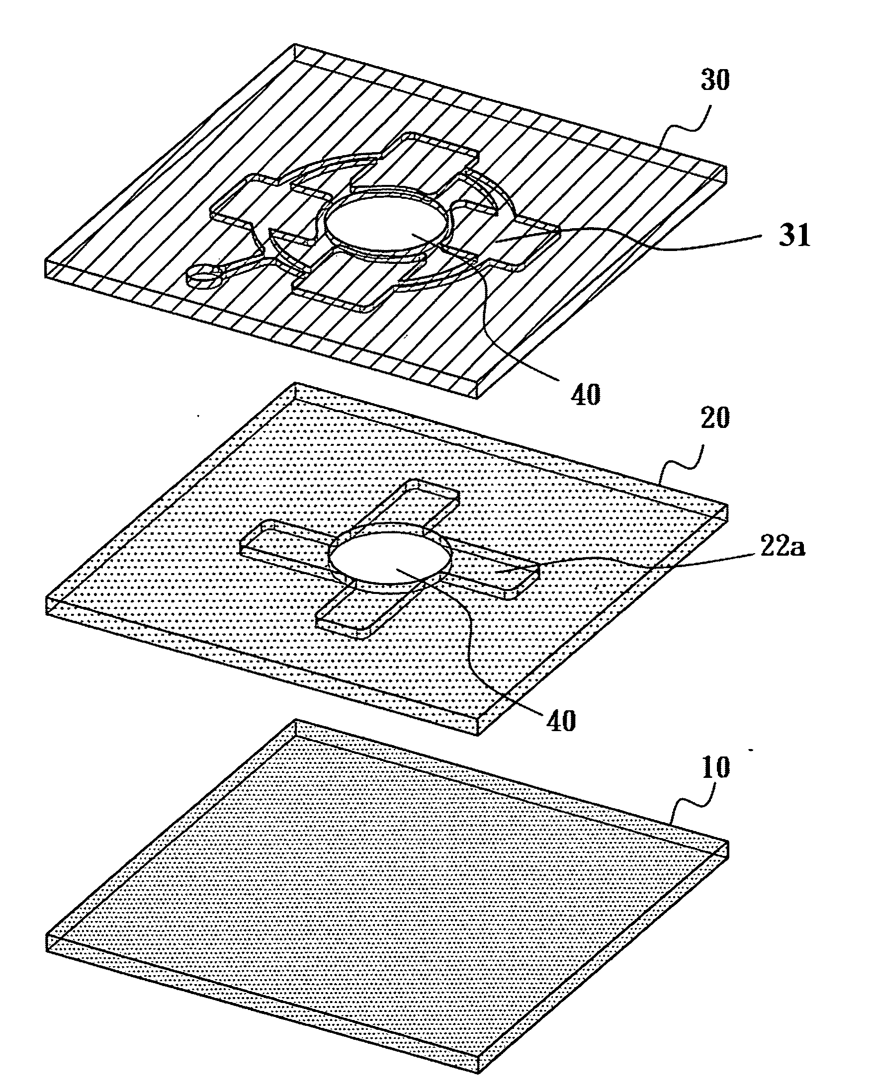
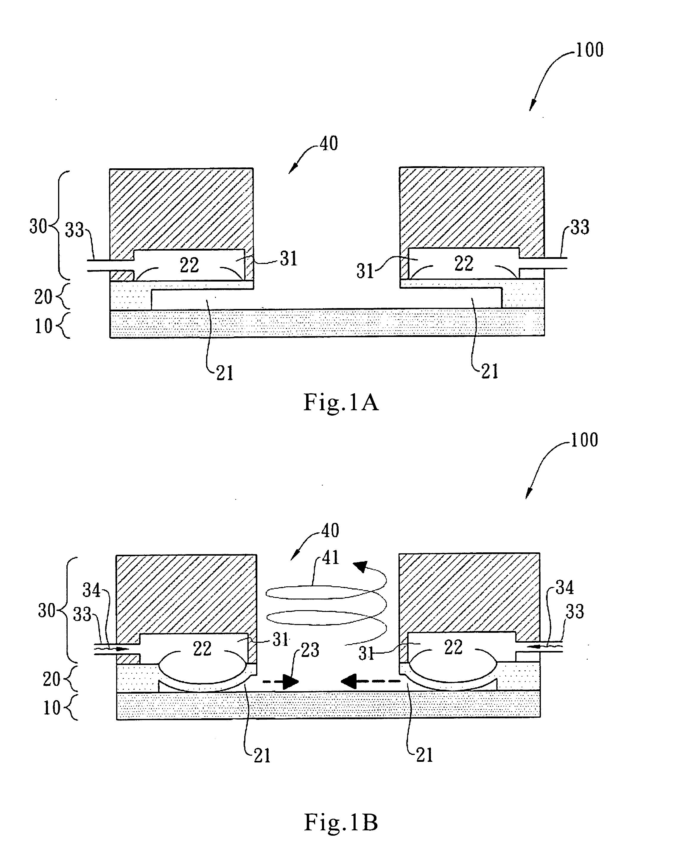
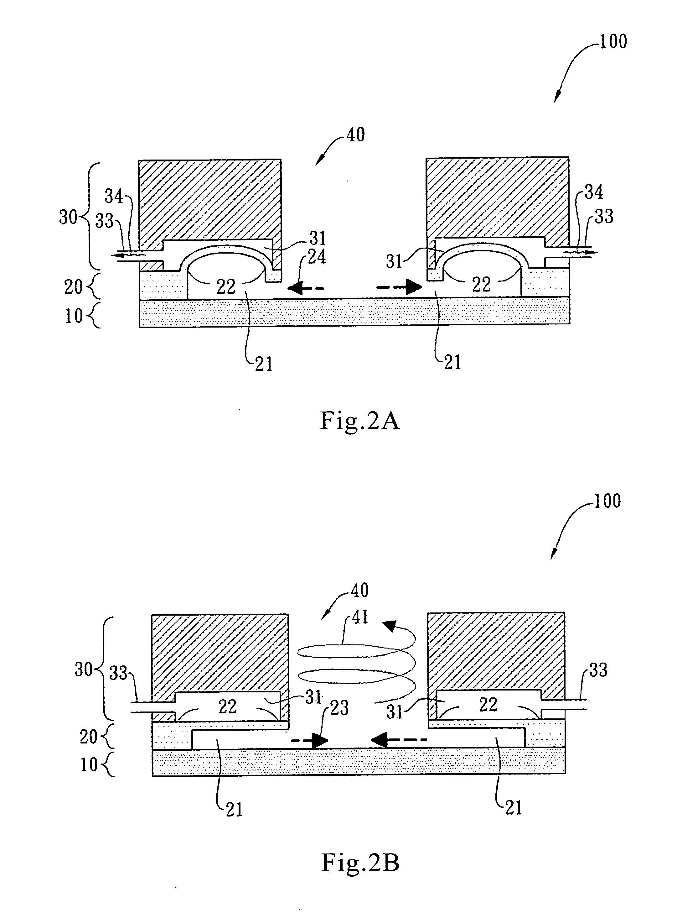
[0041]To evaluate the mixing performance of a micromixer biochip of the present invention, two fluid samples, including red ink and deionized water, are used to demonstrate the mixing process in this embodiment. FIGS. 8, 9, and 10 are referred to for illustrating the mixing process; FIGS. 1 and 7 are referred to for identifying the component numerals of the micromixer biochip.

[0042]FIG. 8 shows a series of photographs for verifying the mixing performance of a micromixer biochip that includes four single-opening fluidic channels; the performance of mixing the deionized water and red ink samples with the same applied pressure at different times are observed. The circular mixing chamber is first loaded with deionized water of 40 μL, and one single-opening fluidic channel is loaded with red ink of 2 μL. The air being injected to the micromixer biochip has an applied pressure of 10 psi and a driving f...


PUM


Abstract

The present invention provides a micromixer biochip, comprising: a substrate having a surface; a fluidic channel layer disposed above the surface of the substrate, including a mixing chamber and a single-opening fluidic channel, wherein one end of the single-opening fluidic channel is closed and the other end of the single-opening fluidic channel connects to the mixing chamber, and a top portion of the single-opening fluidic channel is made of a flexible material; and an air chamber layer disposed above the top portion of the fluidic channel layer, including an air pore, at least one chamber, and an air channel connecting the chamber and the air pore, wherein the number and position of the air chamber correspond to the number and position of the single-opening fluidic channel of the fluidic channel layer

Description

BACKGROUND OF THE INVENTION[0001]1. Field of the Invention[0002]The present invention relates to a micromixer biochip, and more particularly, to a micromixer biochip that mixes the fluids inside the mixing chamber by generating vortex flows.[0003]2. Description of the Related Art[0004]Fluid mixing is an essential procedure in the filed of biochemistry. Thus, to develop micromixers that are simple in design yet can achieve effective mixing within a short time has been an important issue for biochip researchers. Most of the conventional micromixers use passive methods to mix substances. For example, in such a conventional micromixer, more than two substances flowing inside the device are mixed through the use of a blocking or bending structure. This kind of mixing technique is not favorable for biochemical applications, since the mixing performance is generally poor and it consumes much time for substances to be completely mixed.[0005]In recent years, more and more researches in the b...

Claims


Application Information

Patent Timeline
Patent Type & Authority Applications(United States)
IPC IPC(8): B01F5/06B01F13/02B01F33/40
CPCB01F5/0068B01F13/0059B01F11/0071B01F25/104B01F31/65B01F33/30
Inventor LEE, GWO-BINYANG, SUNG-YI
Owner NAT CHENG KUNG UNIV
Why Eureka
Try Eureka