Image encoding method and image decoding method

a technology of applied in the field of moving image encoding and decoding processes, can solve the problems of inability to improve image quality, limit the amount of compression/decompression delay that can be lowered, and transmission buffer delay caused by the virtual buffer model operating in the unit of pictures

Active Publication Date: 2010-09-30
KK TOSHIBA
View PDF8 Cites 187 Cited by
  • Summary
  • Abstract
  • Description
  • Claims
  • Application Information

AI Technical Summary

Problems solved by technology

However, because it is necessary to guarantee the transmission in the transmission model having the smallest transmission bandwidth among the plurality of bandwidths, it is not possible to improve the image quality by effectively utilizing the bandwidths in the transmission channels having larger transmission bandwidths.
In addition, like in the conventional reception buffer model according to MPEG-2 or the like, because buffer control is exercised in units of pictures, there is a limit to how much compression / decompression delay can be lowered.
As explained above, in the conventional moving image encoding methods according to MPEG-2, H.264, and the like, the transmission buffer delay caused by the virtual buffer model operating in units of pictures also occurs in addition to the delays in the encoding process and the decoding process.
Thus, a large display delay occurs in real-time image transmission that involves compressions and decompressions.
Furthermore, in the conventional low-delay modes, problems remain where frame skipping occurs and where it is necessary to use a transmission channel having a larger bandwidth than required by an encoded data amount.

Method used


Image

  • Image encoding method and image decoding method
  • Image encoding method and image decoding method
  • Image encoding method and image decoding method

Examples


first embodiment

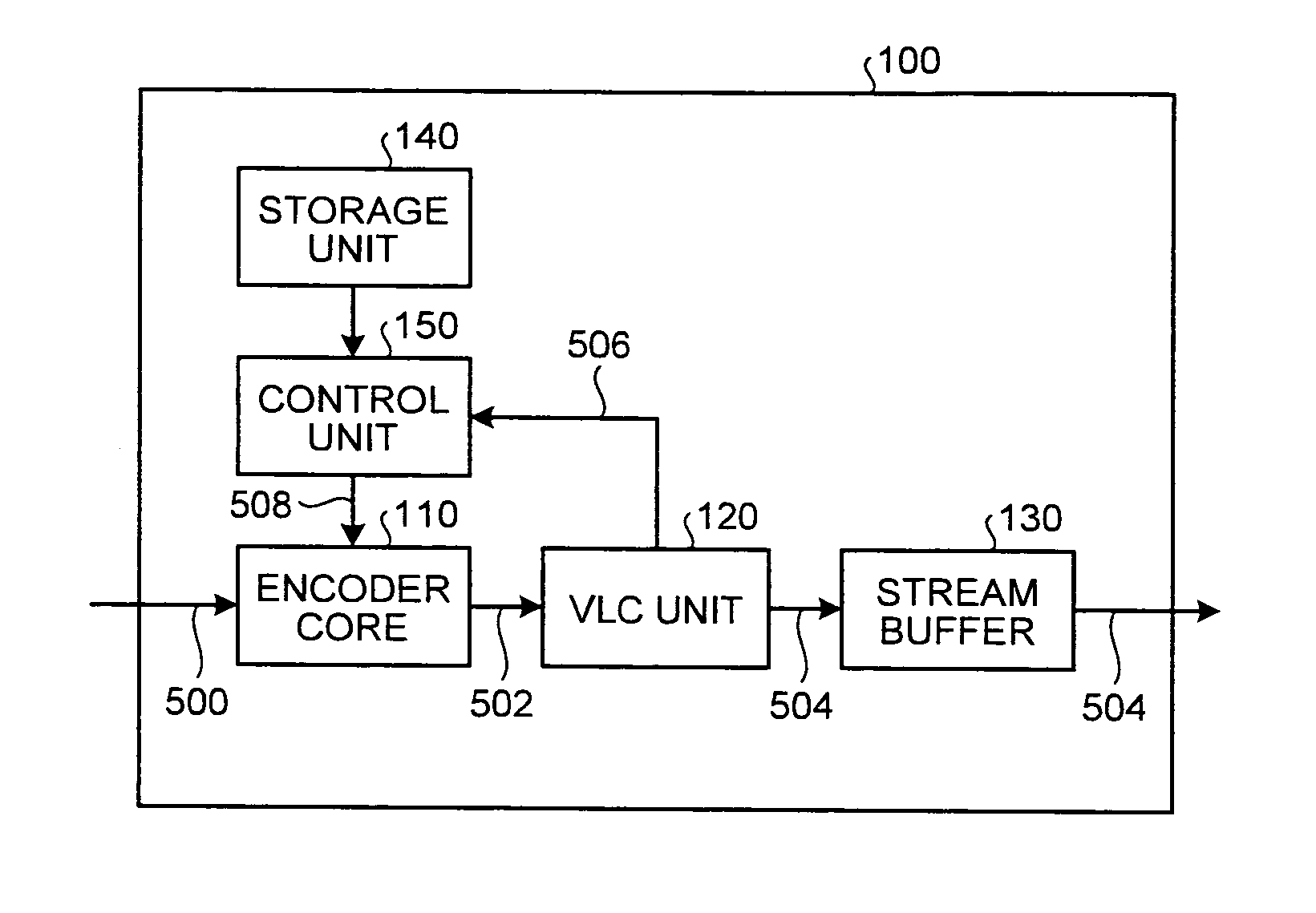
[0038]Exemplary embodiments of the present invention will be explained. An encoder according to the present invention performs a moving image encoding process that uses intra-frame predictions or inter-frame predictions. Also, during the encoding process, the encoder generates and outputs encoded data that a decoder is able to decode and display not only in units of pictures, but also in units of slices. As shown in FIG. 1, an encoder 100 includes an encoder core 110; a Variable Length Code (VLC) unit 120; a stream buffer 130; a storage unit 140; and a control unit 150. Under the control of the control unit 150, the encoder core 110 acquires an input image signal 500 and divides the input image signal 500 into slices. Further, the encoder core 110 performs signal processing, such as a Discrete Cosine Transform (DCT), that is related to the encoding process.

[0039]The VLC unit 120 acquires data 502 resulting from the process performed by the encoder core 110, performs an entropy encod...

second embodiment

[0117]As shown in FIG. 22, an encoder 101 includes a first encoder core 111, a first VLC unit 121, a first stream buffer 131, a second encoder core 112, a second VLC unit 122, a second stream buffer 132, a storage unit 140, a control unit 151, and a selector 160.

[0118]The first encoder core 111 and the second encoder core 112 perform regular encoding processes under the control of the control unit 151. The control unit 151 sets mutually different encoding parameters 508 and 518 (e.g., mutually different quantization parameters) into the first encoder core 111 and the second encoder core 112, respectively. The first encoder core 111 and the first VLC unit 121 generate first encoded data 504 by using a first parameter and temporarily store the first encoded data 504 into the first stream buffer 131. Similarly, the second encoder core 112 and the second VLC unit 122 generate second encoded data 514 by using a second parameter and temporarily store the second encoded data 514 into the ...


PUM


Abstract

A moving image encoding method includes outputting encoded data that comprises an image code sequence corresponding to slices of a moving image and first timing information indicating times at which the slices are to be decoded.

Description

CROSS-REFERENCE TO RELATED APPLICATIONS[0001]This application is based upon and claims the benefit of priority from the prior Japanese Patent Application No. 2009-074983, filed on Mar. 25, 2009; the entire contents of which are incorporated herein by reference.BACKGROUND OF THE INVENTION[0002]1. Field of the Invention[0003]The present invention relates to encoding and decoding processes of moving images.[0004]2. Description of the Related Art[0005]International Organization for Standardization (ISO) / International Electrotechnical Commission (IEC) 13818-2 (hereinafter, “Moving Picture Experts Group (MPEG) 2”) and International Telecommunication Union-Telecommunication Standardization Sector (ITU-T) Recommendation H.264 (hereinafter, “H.264”), both of which are widely known as an international standard for moving image encoding processes, define an image frame or an image field, each of which is a unit of compression, as a “picture”. Each “picture” is used as an access unit in encodin...

Claims


Application Information

Patent Timeline
Patent Type & Authority Applications(United States)
IPC IPC(8): H04N7/26H04N19/00H04N19/115H04N19/15H04N19/174H04N19/196H04N19/70
CPCH04N19/00193H04N19/44H04N21/44004H04N21/8547H04N21/23406H04N19/50H04N19/176H04N19/70H04N19/172H04N19/46H04N19/102H04N19/61H04N19/60H04N19/124H04N19/132H04N19/146H04N19/152H04N19/174H04N21/2401
Inventor KOTO, SHINICHIROYAMAKAGE, TOMOO
Owner KK TOSHIBA
Why Eureka
Try Eureka