Liquid tank and fuel cell
- Summary
- Abstract
- Description
- Claims
- Application Information
AI Technical Summary
Benefits of technology
Problems solved by technology
Method used
Image

Examples
first embodiment
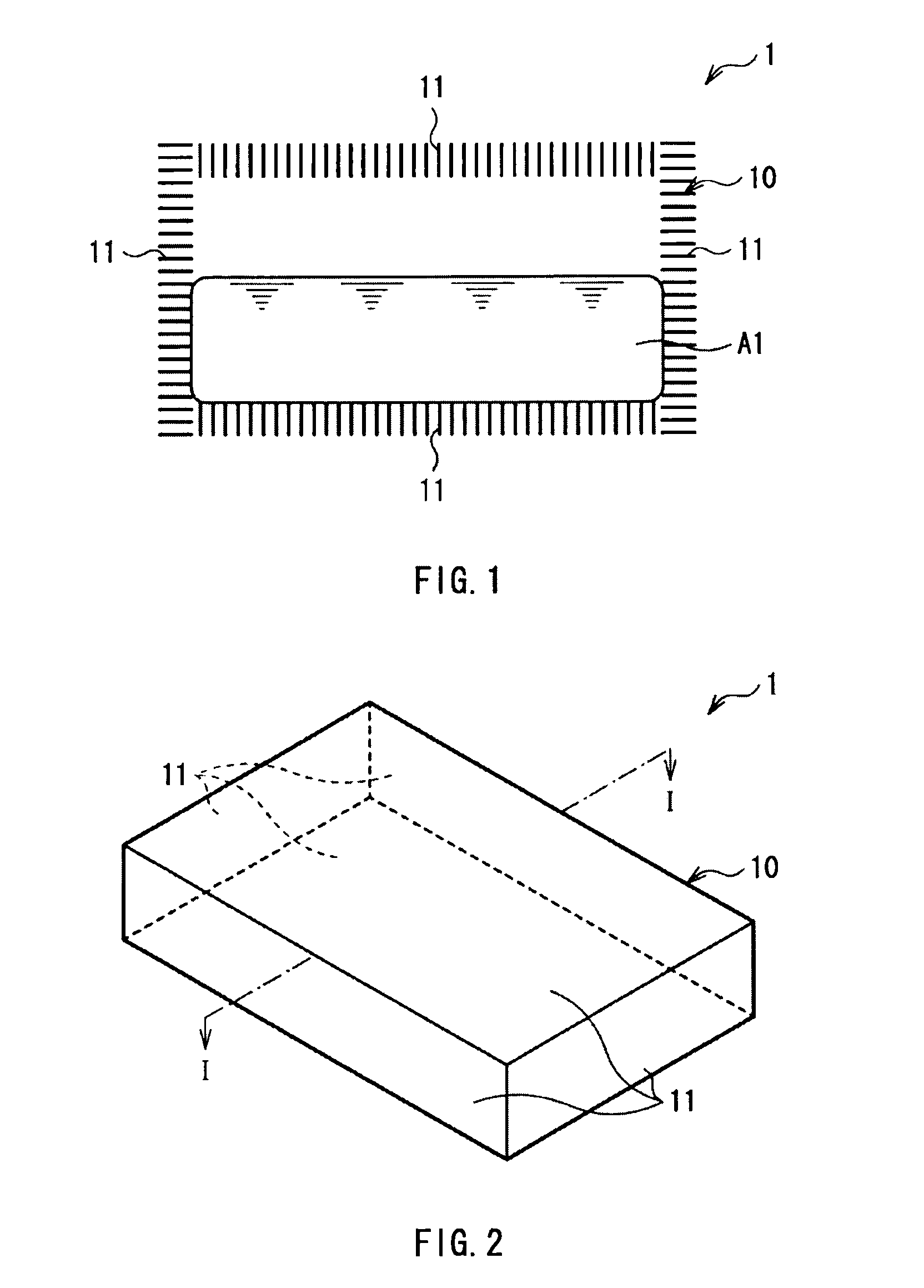
[0056]FIG. 1 illustrates a sectional configuration of a liquid tank according to a first embodiment of the present invention. FIG. 2 expresses the appearance of the liquid tank illustrated in FIG. 1. A liquid tank 1 is used, for example, as a fuel tank of a fuel cell and has a liquid-repellent casing 10.
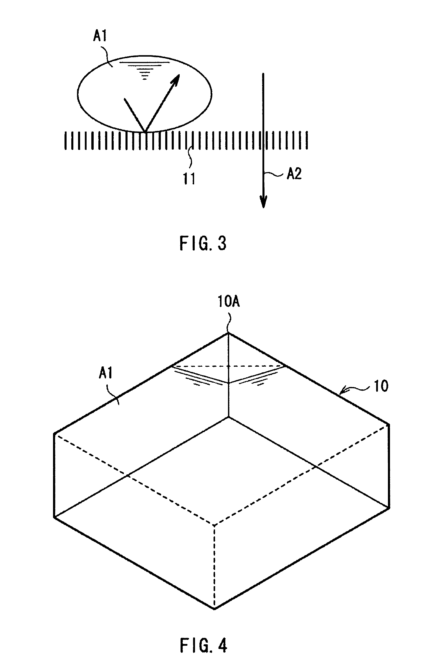
[0057]The liquid-repellent casing 10 has, for example, a rectangular parallelepiped shape. All of six faces of the liquid-repellent casing 10 are made of a liquid-repellent material 11 having pores through which gas passes. Consequently, in the liquid tank 1, the inner pressure may be maintained constant even in a state where the liquid-repellent casing 10 is inclined at any angle.
[0058]The liquid-repellent material 11 has low wettability to liquid, that is, cosine of a contact angle θ of the liquid is negative. Therefore, since liquid is not entered by capillary force, the inside of the liquid-repellent material 11 is always filled with gas. That is, as illustrated in FIG. 3, the li...
second embodiment
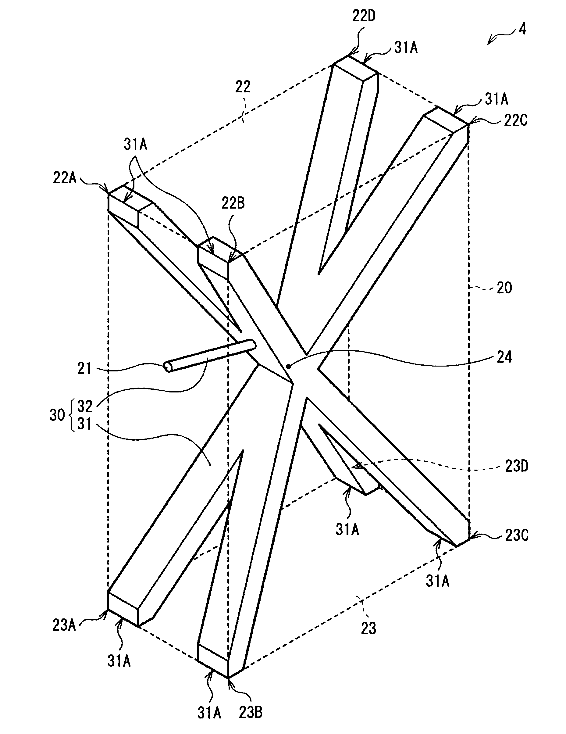
[0066]FIG. 5 illustrates a sectional configuration of a liquid tank 2 according to a second embodiment of the invention. The liquid tank 2 is constructed in a manner similar to the liquid tank 1 described in the first embodiment except that an outside casing 20 covering the outer faces of the liquid-repellent casing 10 is provided. Therefore, the same reference numerals are designated to corresponding components.
[0067]The liquid-repellent casing 10 and the liquid-repellent material 11 are constructed in a manner similar to the first embodiment.
[0068]The outside casing 20 is provided to improve impact resistance of the liquid tank 2. When strong vibration, impact, or the like is applied to the liquid A1 on the inside (that is, when large acceleration is applied), a large force is applied to the surface of the liquid-repellent material 11 (the force is proportional to the acceleration). When the force exceeds the capillary force, the liquid A1 enters the liquid-repellent material 11 a...
third embodiment
[0077]FIG. 6 illustrates a sectional configuration of a liquid tank according to a third embodiment of the invention. In the embodiment, by properly controlling the shape of a void in the liquid-repellent material 11, the liquid A1 entering the inside of the liquid-repellent material 11 is made autonomously ejected. Except for this, a liquid tank 3 of the embodiment is constructed in a manner similar to the liquid tank 2 described in the second embodiment. Therefore, the same reference numerals are designated to corresponding components.
[0078]Concretely, in the liquid-repellent material 11 of the embodiment, as illustrated in FIG. 7A, the shape of a void varies in opposing directions 11C (face perpendicular directions) of a surface 11A and a back face 11B. Consequently, the capillary force in the surface 11A is smaller than that in the back face 11B. That is, the capillary force of the liquid-repellent material 11 inclines in the face perpendicular directions.
[0079]In this case, as ...
PUM
 Abstract
Description
Claims
Application Information
 - R&D
- Intellectual Property
- Life Sciences
- Materials
- Tech Scout
- Unparalleled Data Quality
- Higher Quality Content
- 60% Fewer Hallucinations
Browse by: Latest US Patents, China's latest patents, Technical Efficacy Thesaurus, Application Domain, Technology Topic, Popular Technical Reports.
© 2025 PatSnap. All rights reserved.Legal|Privacy policy|Modern Slavery Act Transparency Statement|Sitemap|About US| Contact US: help@patsnap.com