Robust Self Testing of a Motion Sensor System

Active Publication Date: 2010-10-07
ANALOG DEVICES INC
View PDF2 Cites 38 Cited by
  • Summary
  • Abstract
  • Description
  • Claims
  • Application Information

AI Technical Summary

Benefits of technology

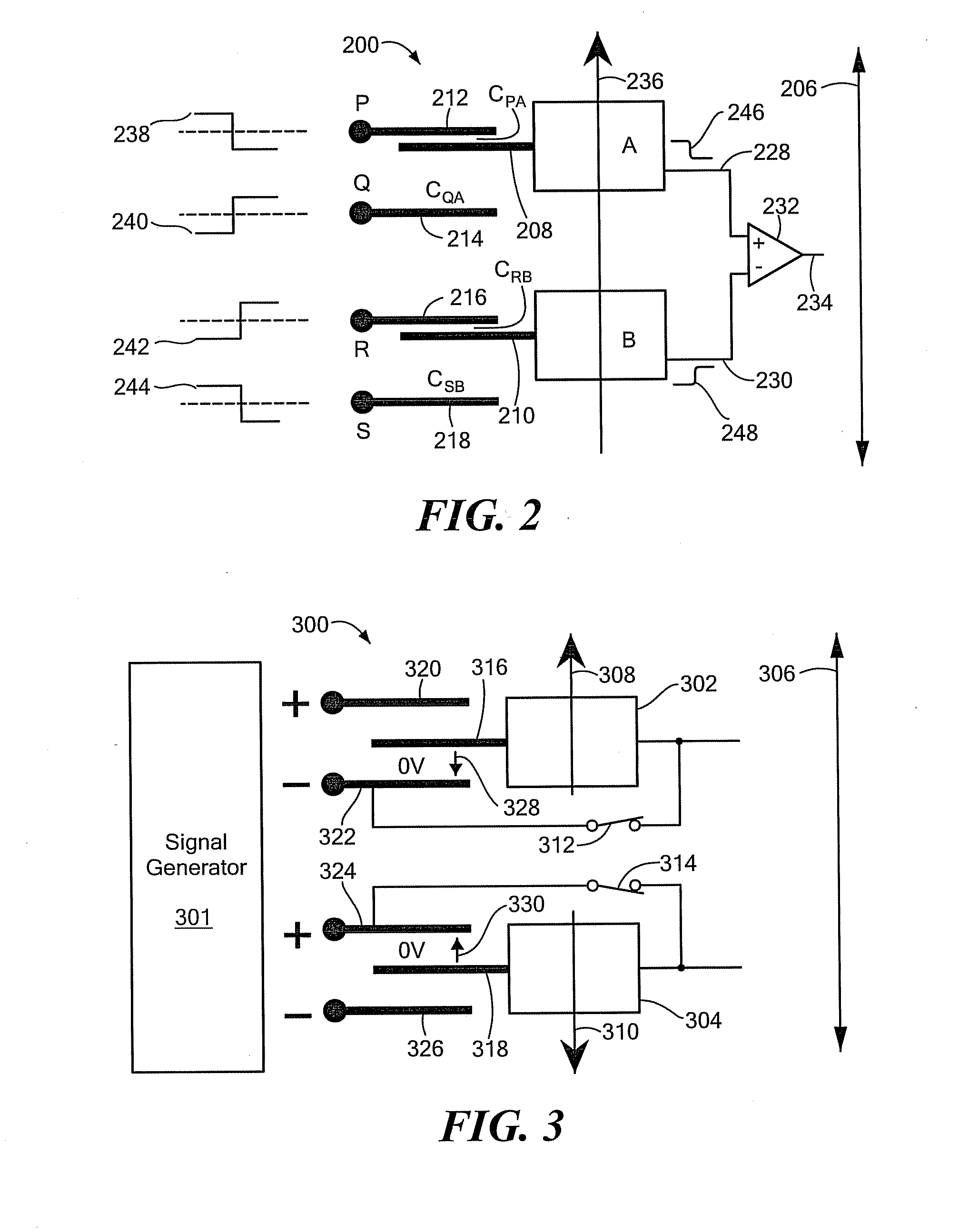
[0016]A first switch may be coupled between the at least one first movable electrode and the at least one first fixed electrode, and a second switch may be coupled between the at least one second movable electrode and the at least one second fixed electrode. A control circuit within the MEMS device may be configured to close the first and second switches for at least part of the time the at least one self-test voltage is applied and to open the first and second switches for at least part of the time the self-test signals are applied.

Problems solved by technology

Any disturbance or movement of the device that affects the two MEMS bodies in the naturally expected manner will be ignored, because such disturbance will result in common mode output.

Method used


Image

  • Robust Self Testing of a Motion Sensor System
  • Robust Self Testing of a Motion Sensor System
  • Robust Self Testing of a Motion Sensor System

Examples


Embodiment Construction

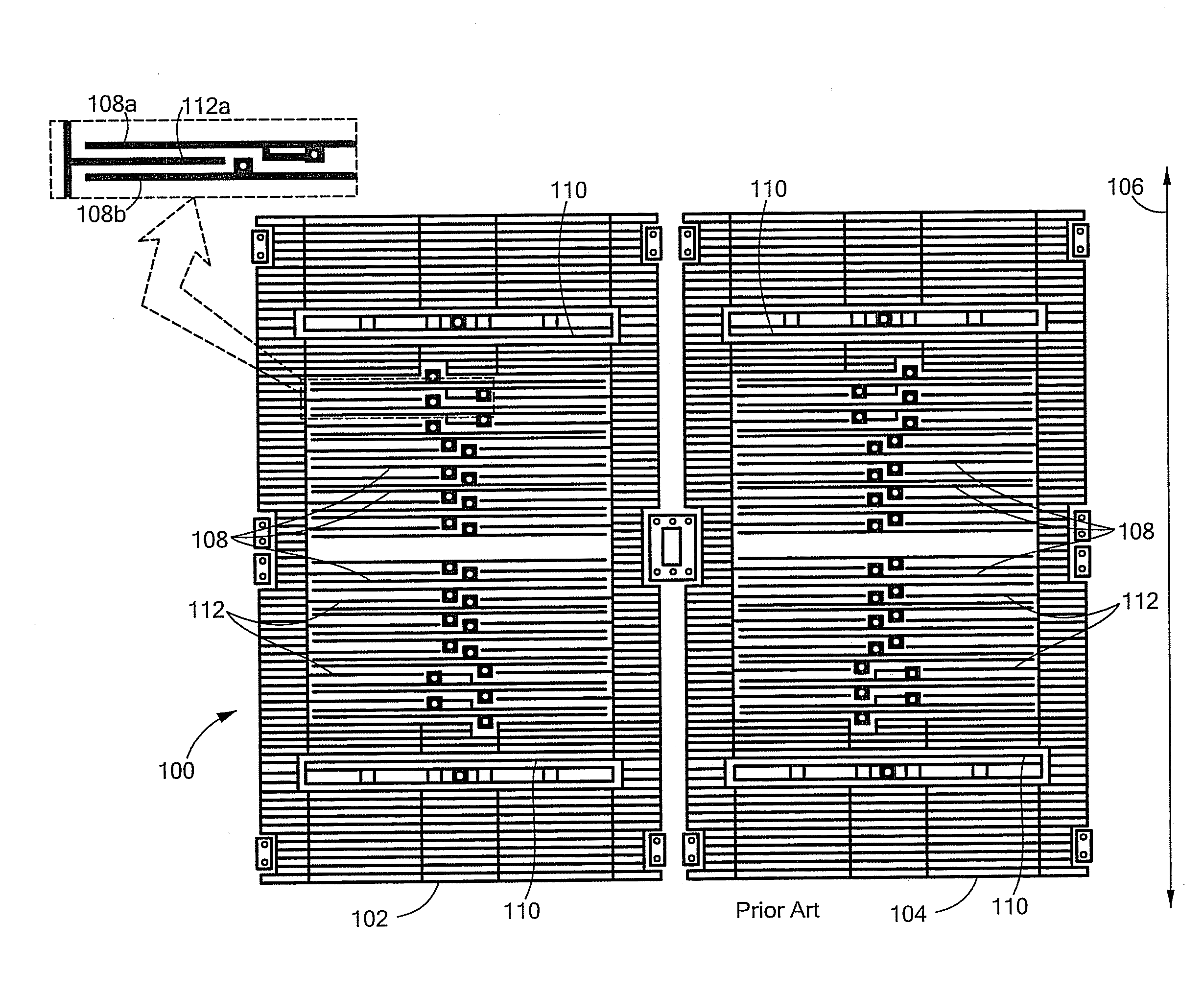
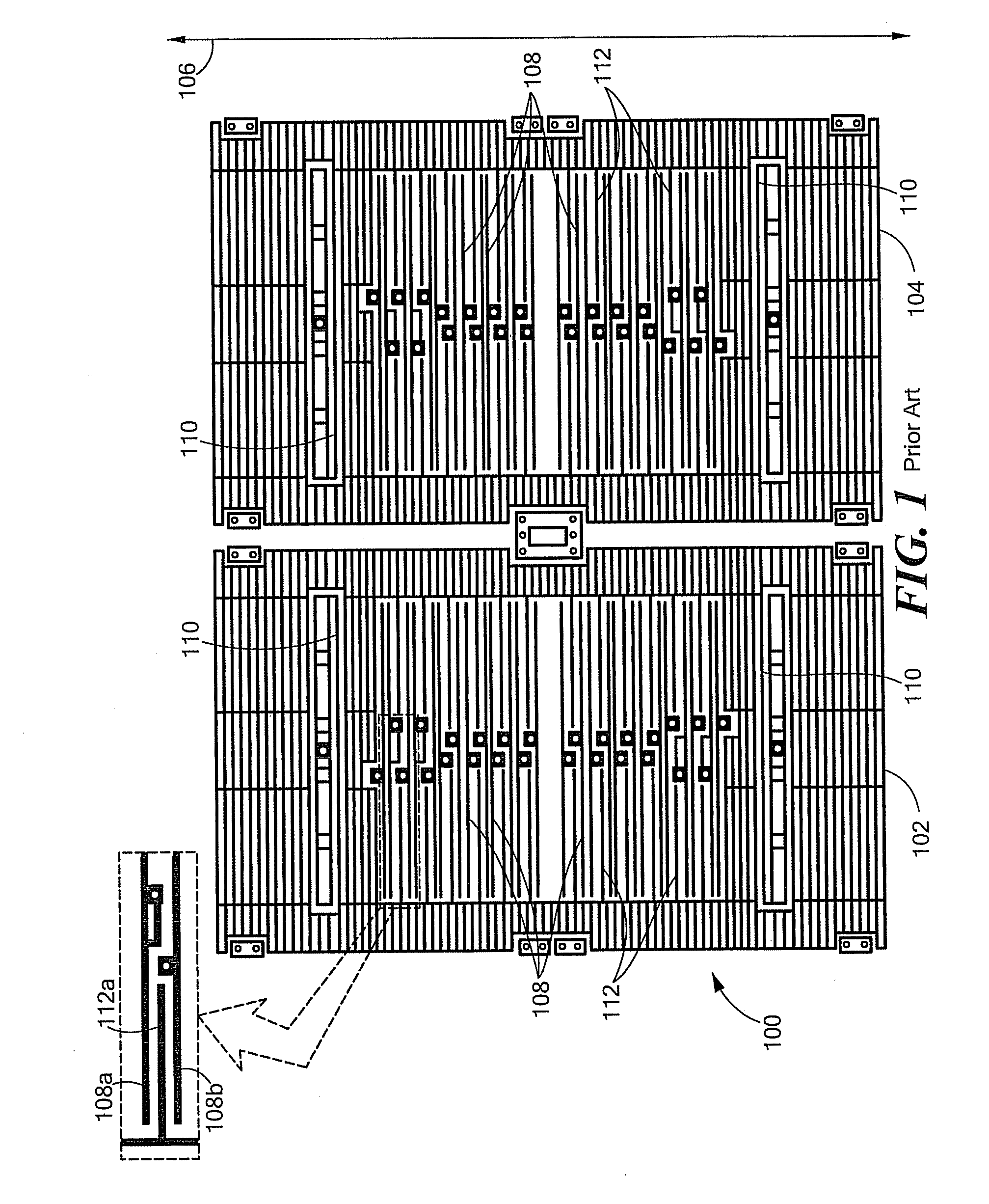
[0027]In accordance with embodiments of the present invention, during testing, an electrical signal (a “self-test voltage”) is applied to a MEMS device under test in an attempt to displace movable masses of the device in an unnatural manner. That is, the self-test voltage is applied in an attempt to cause displacement of the movable masses in a manner that can not naturally occur as a result of physically accelerating the device. Movement or position of the masses is then measured to verify that the masses were displaced as expected and that the device is, therefore, good. In measuring the movement or position of the masses, “self-test signals” (different than the self-test voltage) are applied so as to produce one type of output signal (such as a common mode output) in response to physical acceleration of the device and so as to produce a different type of output signal (such as a differential output signal) in response to the unnatural displacement of the masses. The differential ...


PUM


Abstract

A method for self-testing a dual-mass linear accelerometer in which a self-test voltage is applied to urge the two masses to move in opposite directions. Self-test signals are then applied to obtain a differential mode signal to detect masses repositioned in opposing directions. During testing, common disturbances to the two masses are rejected as common mode signals.

Description

CROSS REFERENCE TO RELATED APPLICATIONS[0001]This application claims the benefit of U.S. Provisional Patent Application No. 61 / 166,583, filed Apr. 3, 2009, titled “Robust Self Testing of a Motion Sensor System,” the entire contents of which are hereby incorporated by reference herein, for all purposesTECHNICAL FIELD[0002]The present invention relates to dual-mass motion sensor systems, and more particularly to self testing of dual-mass MEMS (microelectromechanical system) sensor devices.BACKGROUND ART[0003]It is known in the prior art to self test a MEMS device, such as during a quality control phase of a fabrication process. Some MEMS devices, such as accelerometers, include spring-supported movable masses. In a defective unit, the mass may be immobilized, such as by debris trapped in a space into which the mass is design to move, or the spring may be too stiff or not stiff enough, or the mass may not be sufficiently attached to surrounding structures. In either case, in response t...

Claims


Application Information

Patent Timeline
Patent Type & Authority Applications(United States)
IPC IPC(8): G01P21/00
CPCG01P21/00G01P15/125
Inventor MUECK, MICHAEL
Owner ANALOG DEVICES INC
Why Eureka
Try Eureka