Light adjusting device
a technology of light adjusting device and adjusting coil, which is applied in the direction of optics, instruments, optics, etc., can solve the problems of difficult to achieve stable driving, achieve stable driving, stabilize operation, and reduce the flutter of movable parts
- Summary
- Abstract
- Description
- Claims
- Application Information
AI Technical Summary
Benefits of technology
Problems solved by technology
Method used
Image

Examples
first embodiment
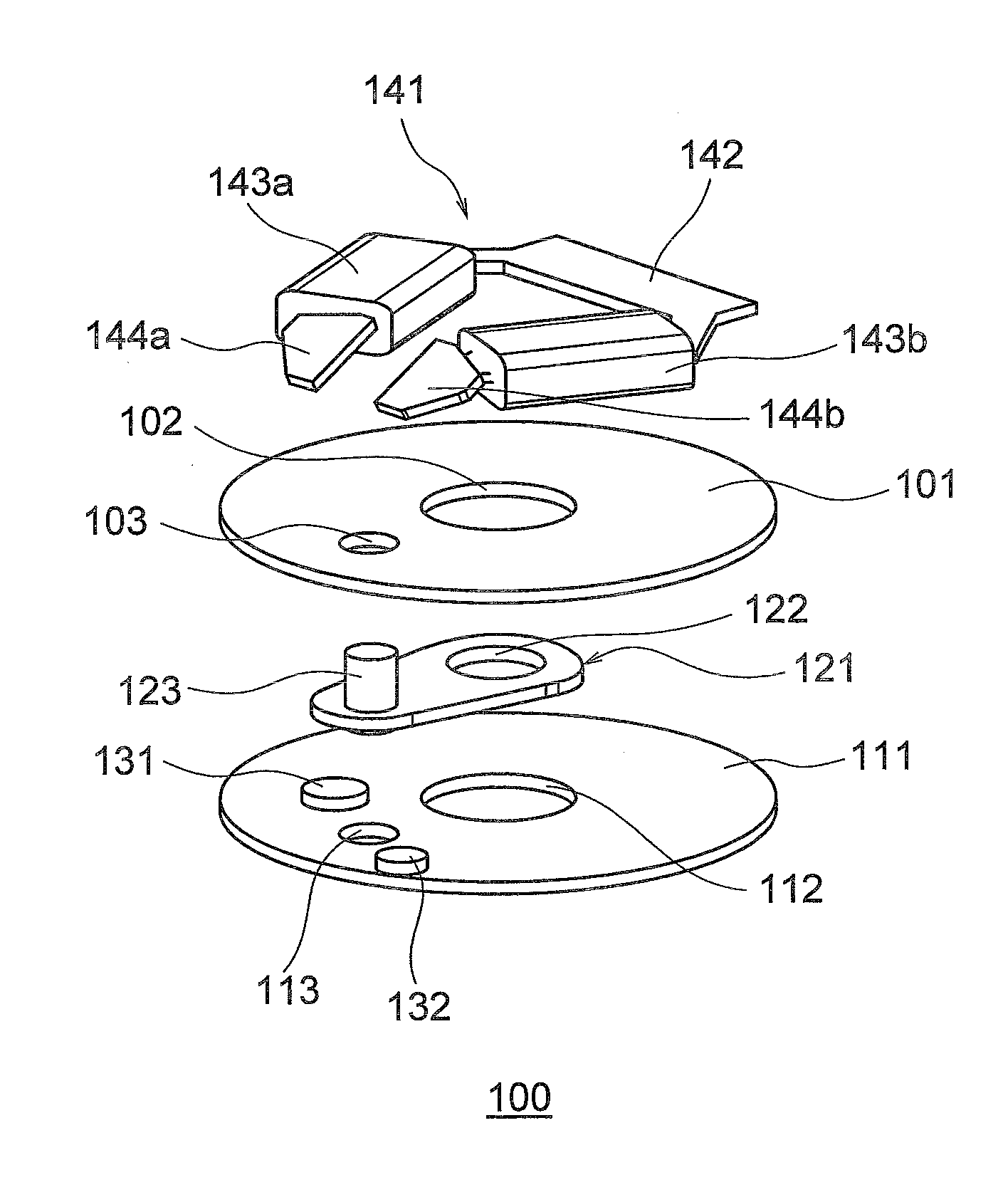
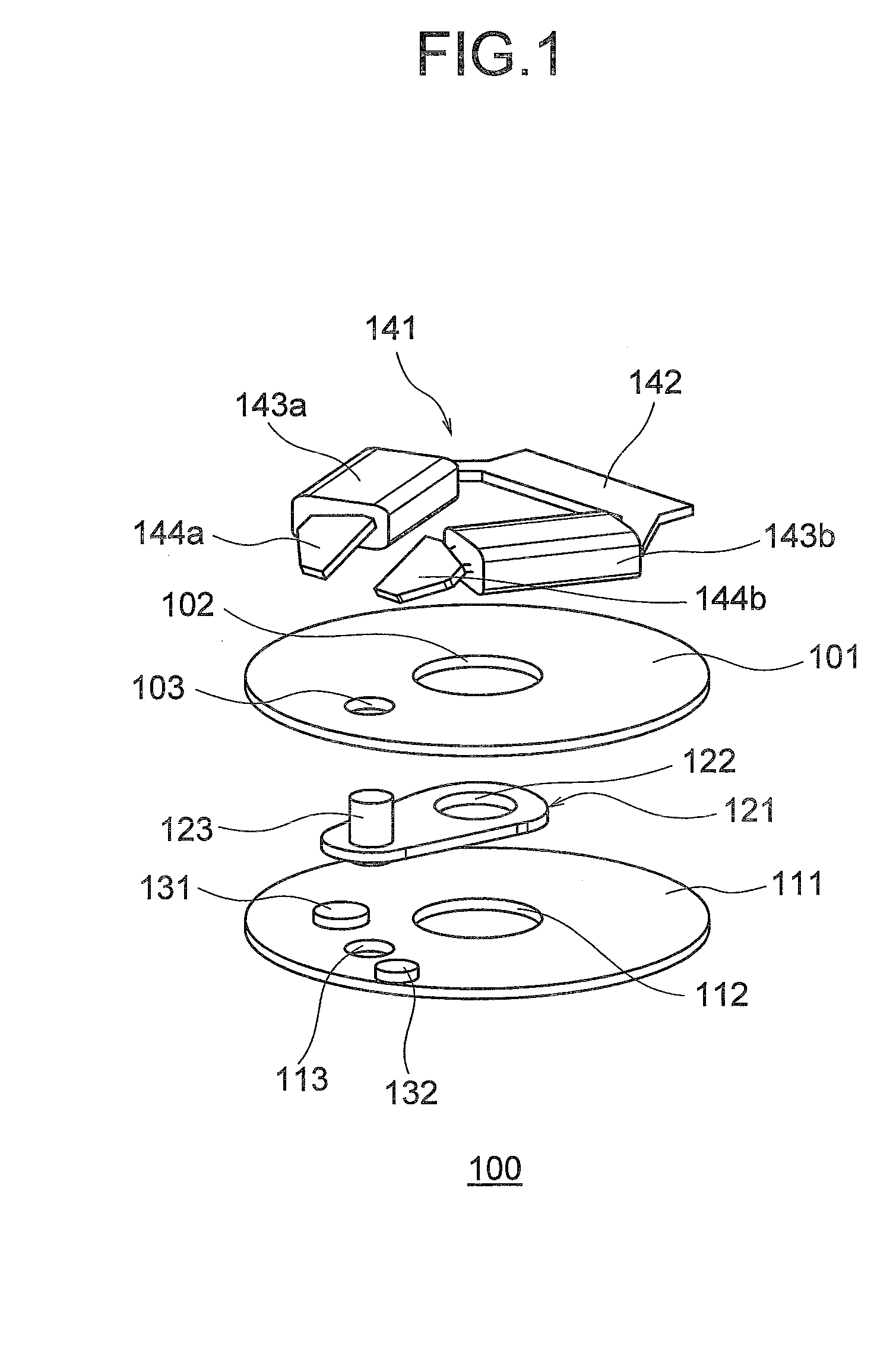
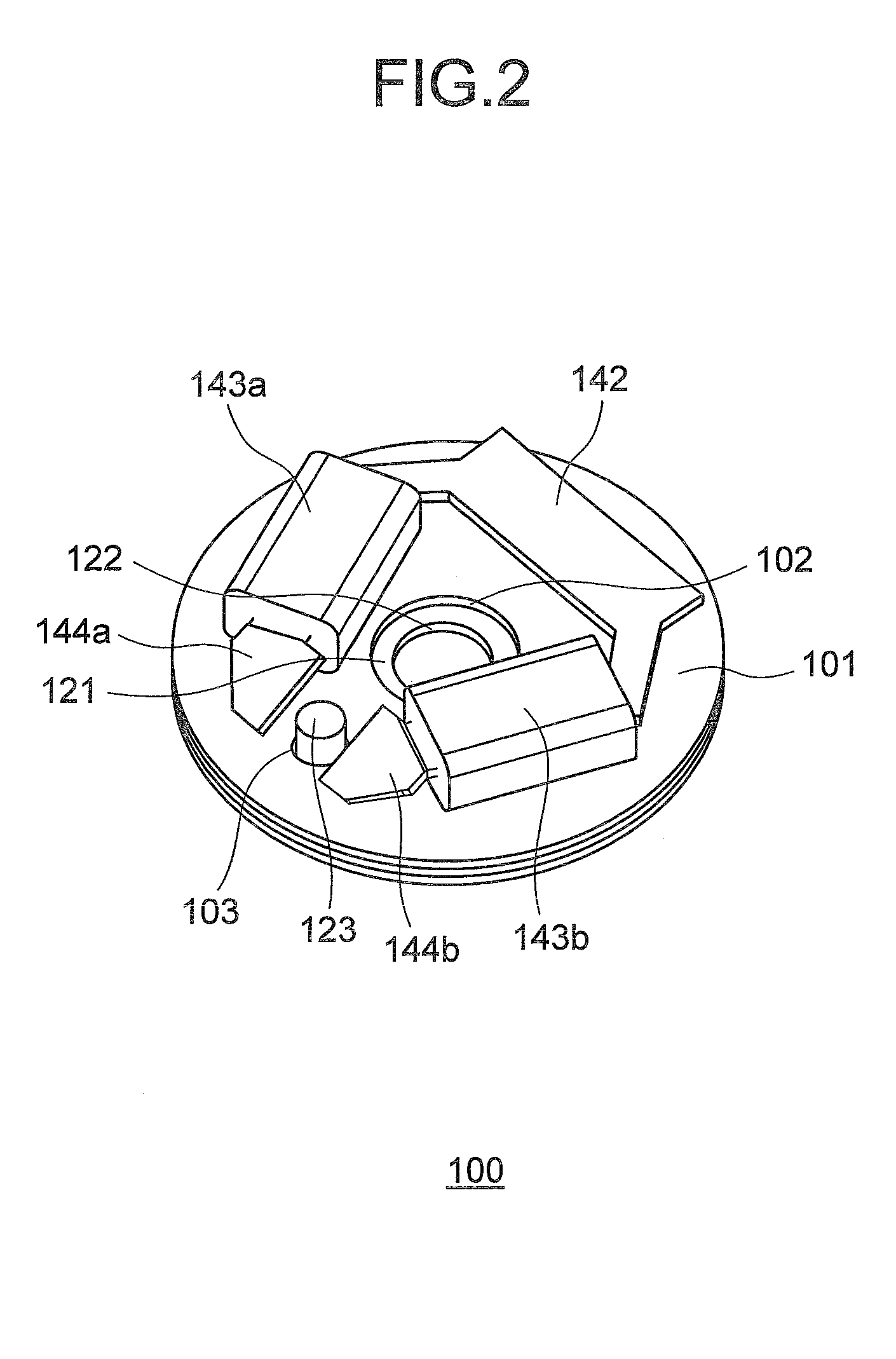
[0036]A light adjusting device 100 according to a first embodiment is explained below with reference to FIGS. 1 to 6. FIG. 1 is an exploded perspective view of the configuration of the light adjusting device 100 according to the first embodiment. FIG. 2 is a perspective view of the configuration of the light adjusting device 100 in an assembled condition.
[0037]The light adjusting device 100 includes a base plate 101 with an optical aperture 102 formed therein, a base plate 111 with an optical aperture 112 formed therein, a plate-shaped light adjusting member 121 with an optical aperture 122 formed therein, two restricting parts 131 and 132 that restrict the movement of the light adjusting member 121, and an electromagnetic driving source 141 for moving the light adjusting member 121. The base plate 101 and the base plate 111 are circular plates with the same outer diameter. The optical aperture 102 is provided at the center of the base plate 101 and the optical aperture 112 is provi...
second embodiment
[0056]A light adjusting device 200 according to a second embodiment is explained below with reference to FIGS. 7 and 8. FIG. 7 is an exploded perspective view of the configuration of the light adjusting device 200. FIG. 8 is a perspective view of the configuration of the light adjusting device 200 in an assembled state. Structural elements in FIGS. 7 and 8 having the same or similar configuration or the same or similar function as the elements in the light adjusting device 100 according to the first embodiment are assigned the same reference numbers and their explanations are omitted.
[0057]An electromagnetic driving source 241 of the second embodiment includes a yoke member 242 (yoke) and winding coils 243a and 243b. The shapes of two front end sections 244a and 244b of the yoke member 242 in the electromagnetic driving source 241 of the second embodiment differ from the shapes of both the front end sections 144a and 144b of the first embodiment.
[0058]Specifically, both the front en...
third embodiment
[0062]A light adjusting device 300 according to a third embodiment is explained below with reference to FIGS. 9 and 10. FIG. 9 is an exploded perspective view of the configuration of the light adjusting device 300. FIG. 10 is a perspective view of the configuration of the light adjusting device 300 in an assembled state. Structural elements in FIGS. 9 and 10 having the same or similar configuration or the same or similar function as the elements in the light adjusting device 100 according to the first embodiment are assigned the same reference numbers and their explanations are omitted.
[0063]An electromagnetic driving source 341 according to the third embodiment includes a yoke member 342 (yoke) and winding coils 343a and 343b. The shapes of two front end sections 344a and 344b of the yoke member 342 in the electromagnetic driving source 341 of the third embodiment differ from the shapes of both the front end sections 144a and 144b of the first embodiment.
[0064]Specifically, both th...
PUM
 Abstract
Description
Claims
Application Information
 - R&D
- Intellectual Property
- Life Sciences
- Materials
- Tech Scout
- Unparalleled Data Quality
- Higher Quality Content
- 60% Fewer Hallucinations
Browse by: Latest US Patents, China's latest patents, Technical Efficacy Thesaurus, Application Domain, Technology Topic, Popular Technical Reports.
© 2025 PatSnap. All rights reserved.Legal|Privacy policy|Modern Slavery Act Transparency Statement|Sitemap|About US| Contact US: help@patsnap.com