Handle, eye, or clothes hook having a mounting plate and pivot bearing

a technology of mounting plate and pivot bearing, which is applied in the direction of wing knobs, furniture parts, manufacturing tools, etc., can solve the problem of not being able to fold away

Active Publication Date: 2010-10-14
RAMSAUER DIETER
View PDF21 Cites 5 Cited by
  • Summary
  • Abstract
  • Description
  • Claims
  • Application Information

AI Technical Summary

Benefits of technology

[0007]It is the object of the invention to modify the known handle in such a way

Problems solved by technology

A drawback of this known handle

Method used


Image

  • Handle, eye, or clothes hook having a mounting plate and pivot bearing
  • Handle, eye, or clothes hook having a mounting plate and pivot bearing
  • Handle, eye, or clothes hook having a mounting plate and pivot bearing

Examples


Embodiment Construction

[0044]It is to be understood that the figures and descriptions of the present invention have been simplified to illustrate elements that are relevant for a clear understanding of the present invention, while eliminating, for purposes of clarity, many other elements which are conventional in this art. Those of ordinary skill in the art will recognize that other elements are desirable for implementing the present invention. However, because such elements are well known in the art, and because they do not facilitate a better understanding of the present invention, a discussion of such elements is not provided herein.

[0045]The present invention will now be described in detail on the basis of exemplary embodiments.

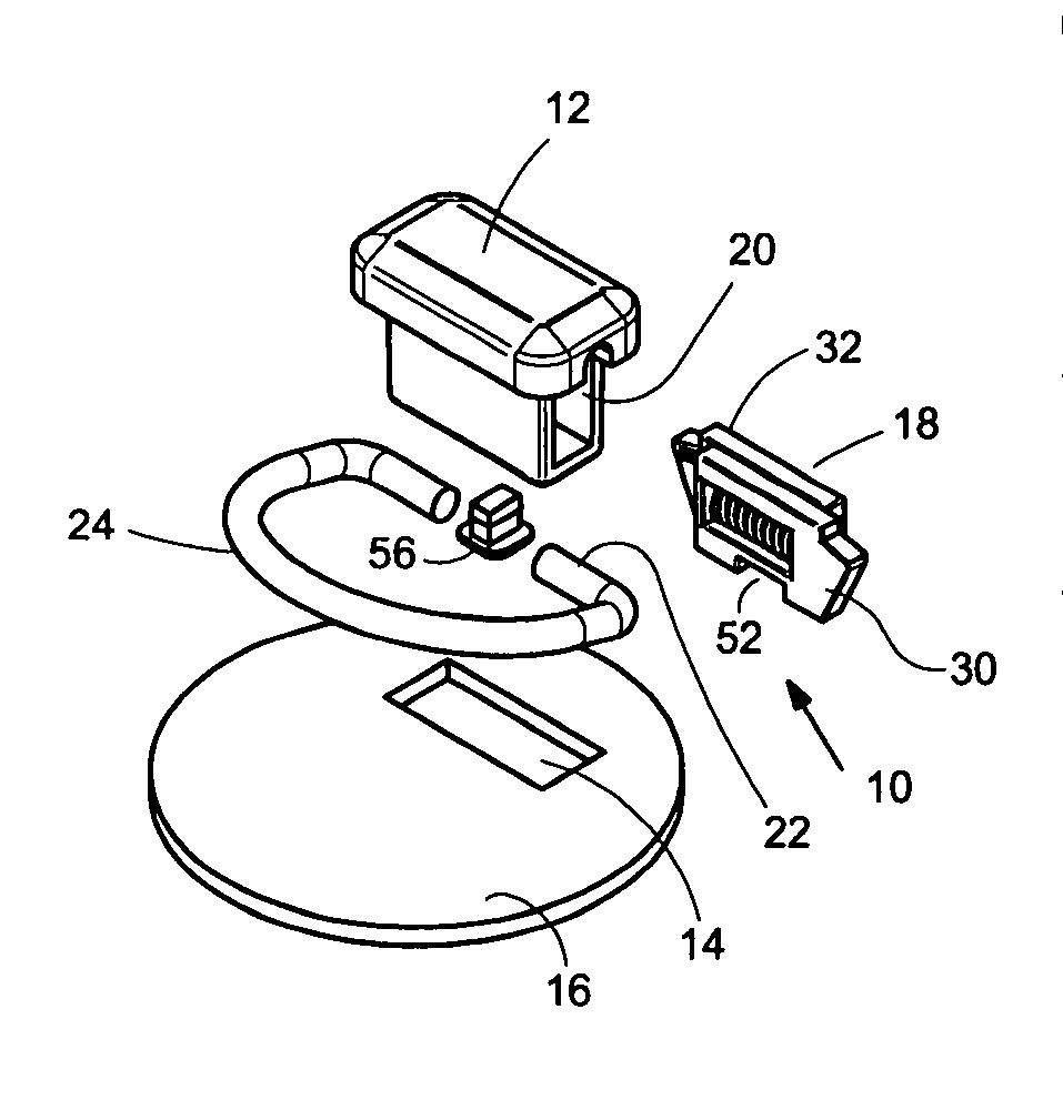
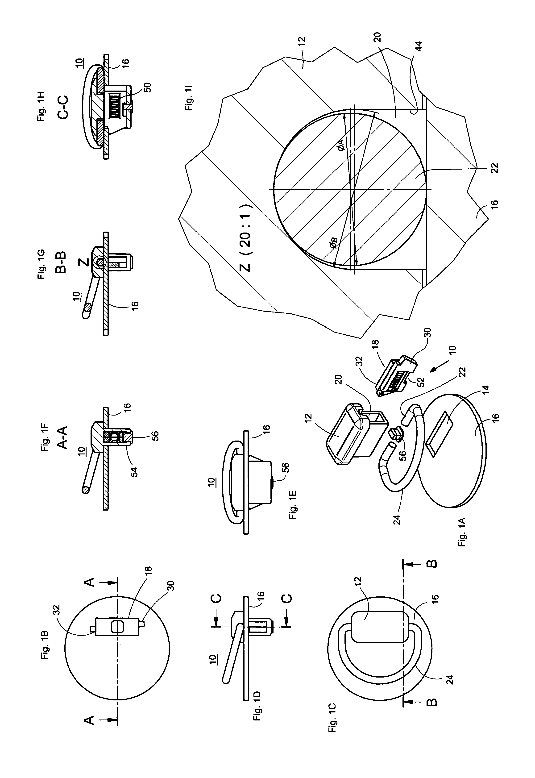
[0046]FIG. 1A is an exploded view of a first embodiment form of a handle or lashing lug designed according to the invention comprising the handle 10 with at least one fastening plate or holding part 12. The fastening plate can be secured in a through-hole 14 in a thin wall 16 s...


PUM


Abstract

A handle has at least one fastening plate or holding part which can be fastened in a through-hole in a thin wall such as a sheet-metal wall by means of snap devices. According to the invention, the fastening plate forms or carries a pivot bearing for the at least one end of a handle, or the like, which is bent, for example, from a round material such as thick wire, this end having a round cross section.

Description

[0001]The present application claims priority from PCT Patent Application No. PCT / EP2008 / 007616 filed on Sep. 13, 2008, which claims priority from German Patent Application No. DE 20 2007 014 728.7 filed on Oct. 19, 2007, the disclosure of which is incorporated herein by reference in its entirety.BACKGROUND OF THE INVENTION[0002]1. Field of the Invention[0003]The invention is directed to a handle or eyelet or clothes hook with at least one fastening plate which can be secured in a through-hole in a thin wall such as a sheet-metal wall by means of snap devices.[0004]2. Description of Related Art[0005]A handle of the type mentioned above is already known from WO2005 / 083207 A1.[0006]A drawback of this known handle is that it cannot be folded away.SUMMARY OF THE INVENTION[0007]It is the object of the invention to modify the known handle in such a way that it can be folded away so that it no longer protrudes in a troublesome manner.[0008]The above-stated object is met in that the fasteni...

Claims


Application Information

Patent Timeline
IPC IPC(8): B25G1/00F16C17/00
CPCY10T16/44E05B1/0015
Inventor RAMSAUER, DIETER
Owner RAMSAUER DIETER
Why Eureka
Try Eureka