Electrical junction box

a junction box and electric technology, applied in the direction of electric discharge tubes, electrical apparatus casings/cabinets/drawers, electrical discharge tubes, etc., can solve the problems of failure to ensure and control, and achieve the effect of facilitating the breakage of the mounting foot and bringing the device into the breakag

Inactive Publication Date: 2010-10-14
YAZAKI CORP
View PDF1 Cites 8 Cited by
  • Summary
  • Abstract
  • Description
  • Claims
  • Application Information

AI Technical Summary

Benefits of technology

[0018]According to the present invention, since the breakage-inducing portion is provided such that the box body is displaced in the displacement direction at the time of the vehicle collision, and that the breakage-inducing portion resides on the displacement trajectory that the fastening bolt may describe, it is possible to make a force at the time of the vehicle collision act effectively on the breakage-inducing portion. Accordingly, an advantageous effect is achieved that the mounting foot can be readily brought into breakage. Also, according to the present invention, another advantageous effect is that determination of arrangement ...

Problems solved by technology

Accordingly, when the breakage-inducing portion 2 of this arrangement is applied to a mounting foot of another type of the electrical junction box, breakage will not always be induced effec...

Method used


Image

  • Electrical junction box
  • Electrical junction box
  • Electrical junction box

Examples


Embodiment Construction

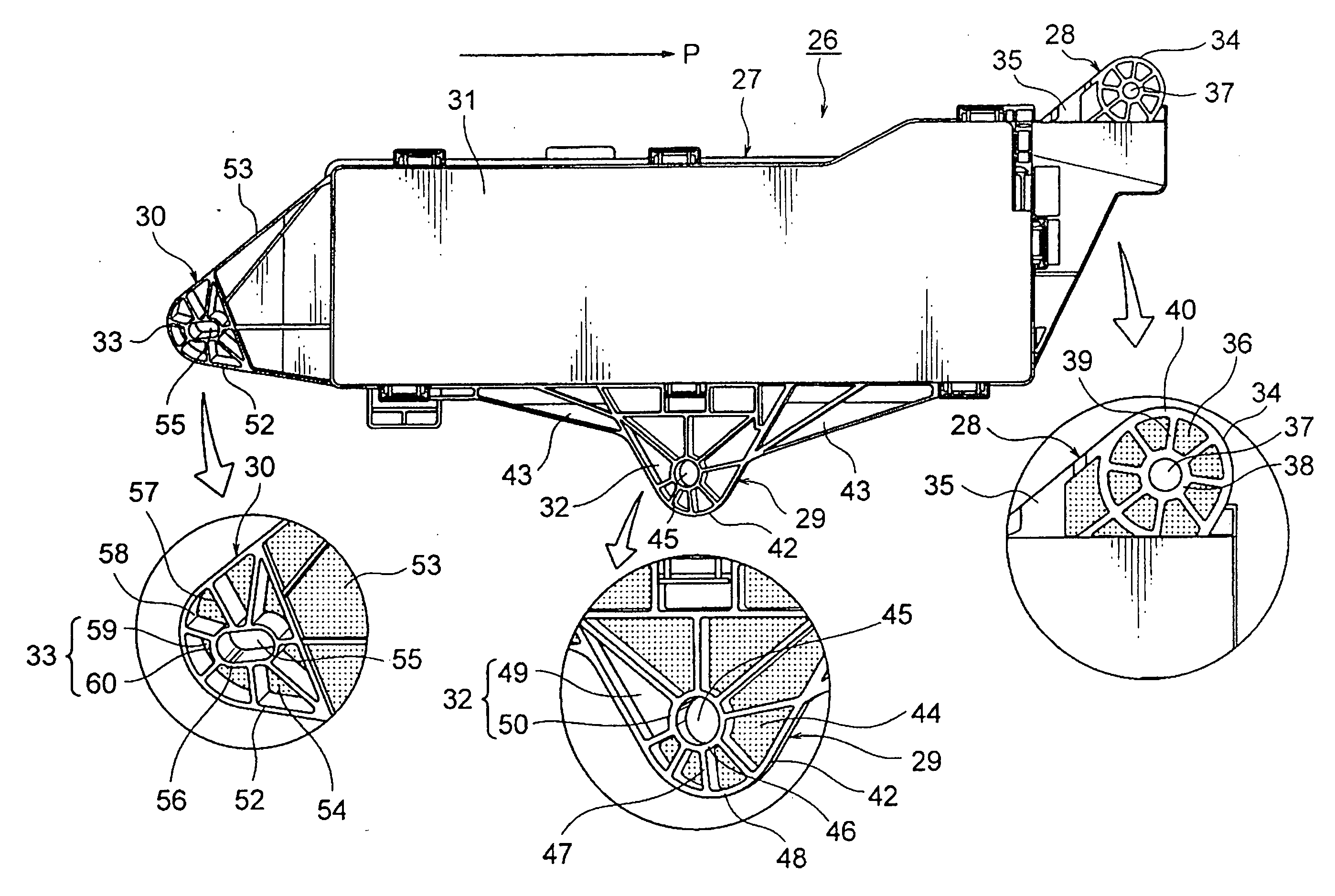
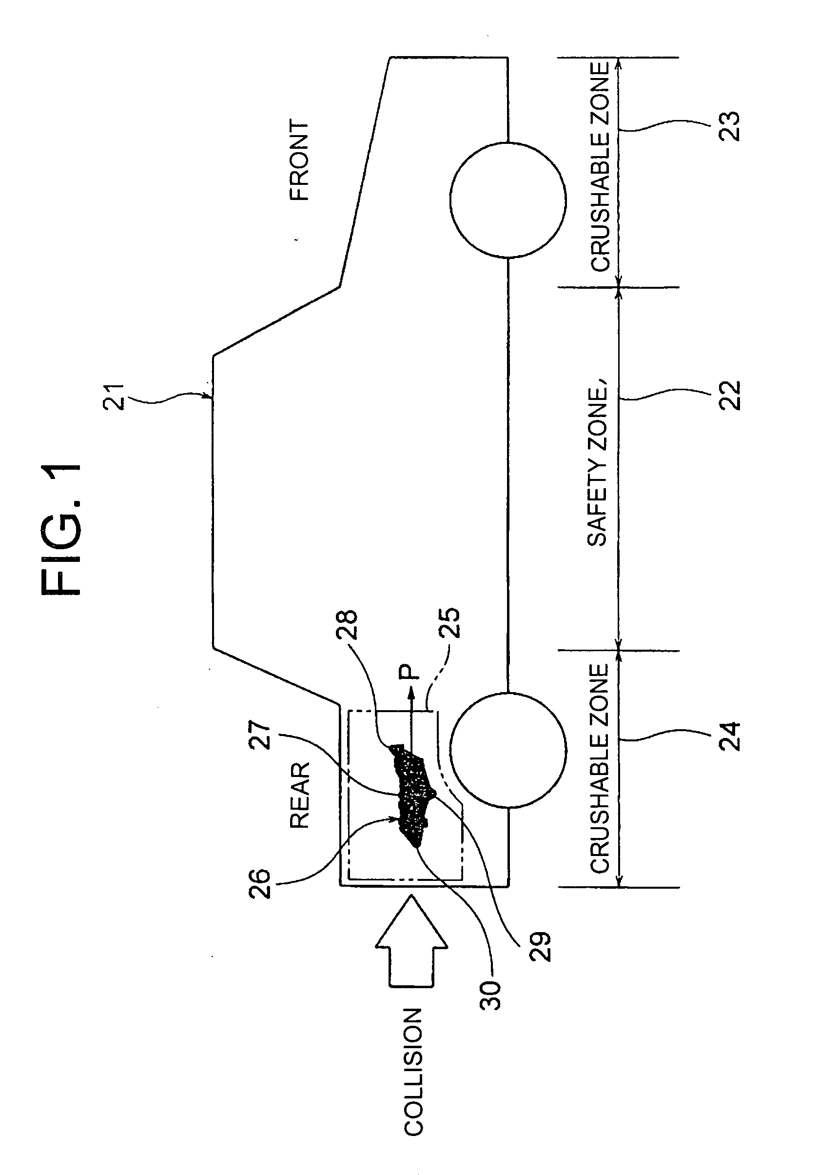
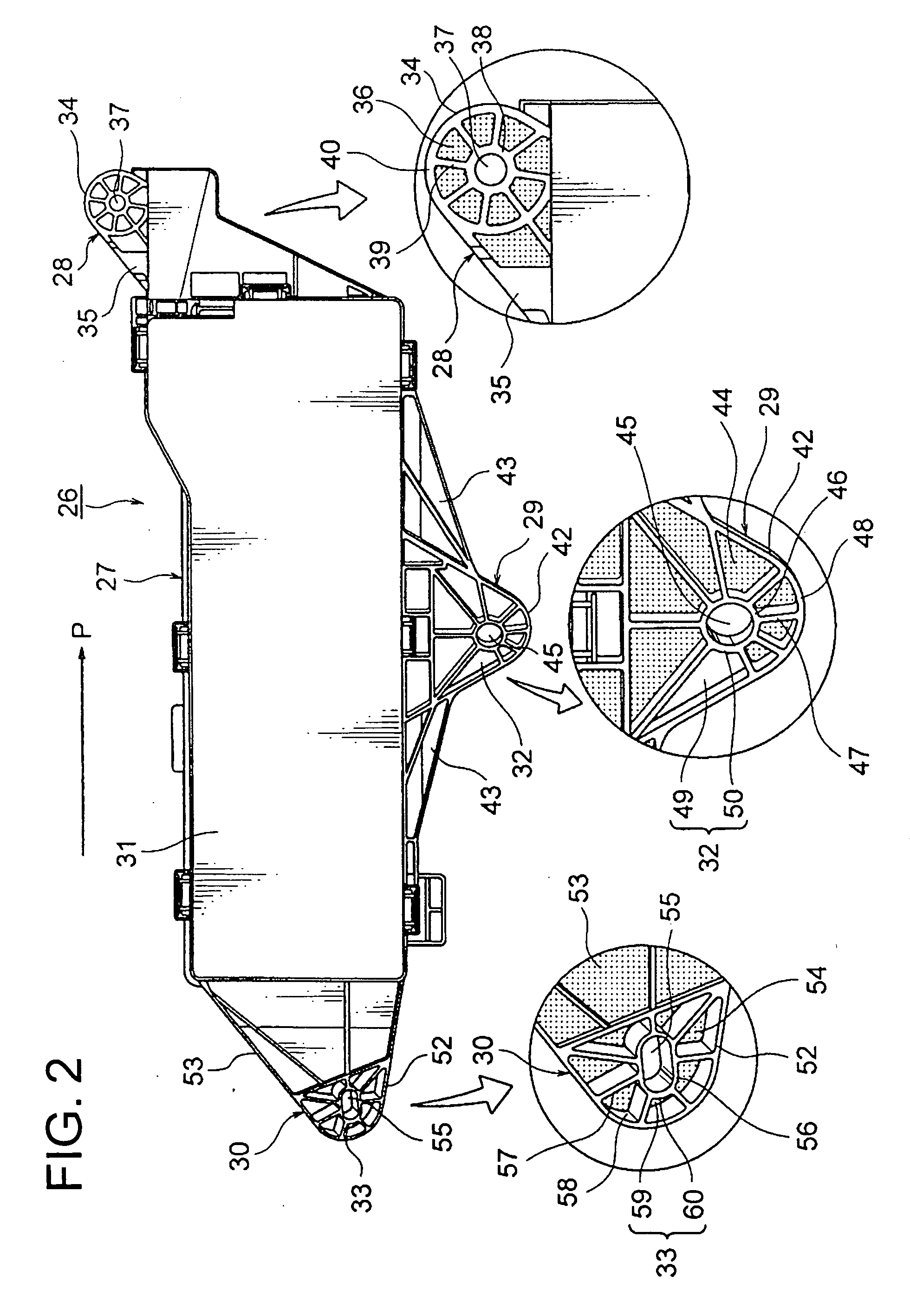
[0026]An electrical junction box of the present invention is configured to be fixed via its mounting foot to a component-fixation section in a crushable zone of a vehicle, the mounting foot including a breakage-inducing portion. The breakage-inducing portion is provided between an insertion hole through which a fastening bolt for fixing the electrical junction box is passed, and an outer edge of the mounting foot. Also, the breakage-inducing portion is provided in a direction in which the box body is displaced when in a vehicle collision, and is provided such that the portion resides on a displacement trajectory that the fastening bolt describes (a trajectory in which the fastening bolt is displaced relative to the box body in the vehicle collision). The breakage-inducing portion residing on the displacement trajectory of the fastening bolt includes a throughhole and a notch.

[0027]In the following, an exemplary embodiment is explained with reference to the drawings. FIG. 1 is a sche...


PUM


Abstract

An electrical junction box is fixed via at least one mounting foot to a component-fixation section in a crushable zone of a vehicle. The mounting foot includes a breakage-inducing portion. The breakage-inducing portion is provided between an insertion hole into which a fastening bolt is inserted for fixation of the electrical junction box, and an outer edge of the mounting foot. The breakage-inducing portion is provided such that a body of the box is displaced in a displacement direction in a vehicle collision, and the breakage-inducing portion resides on a displacement trajectory that the fastening bolt may describe. The breakage-inducing portion provided on the displacement trajectory of the fastening bolt includes a throughhole and a notch.

Description

CROSS REFERENCE TO RELATED APPLICATION[0001]The priority application Japanese Patent Application No. 2009-078197 upon which the present patent application is based is hereby incorporated by reference.BACKGROUND OF THE INVENTION[0002]1. Field of the Invention[0003]The present invention relates to an electrical junction box disposed in and fixed to a crushable zone of a vehicle.[0004]2. Description of the Related Art[0005]In FIG. 5, the shown electrical junction box 1, as described in Japanese Patent Application Laid-Open Publication No. 2005-119331, includes one mounting foot 3 that has a breakage-inducing portion 2 and two mounting feet 4 that do not have a breakage-inducing portion 2. Thus, the electrical junction box 1 is fixed to and inside of an engine compartment 5 via three mounting feet 3 and 4 in two types with / without the breakage-inducing portion.[0006]The illustrated electrical junction box 1 is a relatively large component that has an elongated shape, which is fixed insi...

Claims


Application Information

Patent Timeline
IPC IPC(8): H05K5/00
CPCH05K5/0234H05K5/0073
Inventor KIYOTA, HIROTAKA
Owner YAZAKI CORP
Why Eureka
Try Eureka