Resistive-switching memory elements having improved switching characteristics

Active Publication Date: 2010-10-14
INTERMOLECULAR
View PDF49 Cites 123 Cited by
  • Summary
  • Abstract
  • Description
  • Claims
  • Application Information

AI Technical Summary

Problems solved by technology

Flash memory is proving, in many instances, to be inadequate for non-volatile memory needs.
Existing resistive-switching memori

Method used


Image

  • Resistive-switching memory elements having improved switching characteristics
  • Resistive-switching memory elements having improved switching characteristics
  • Resistive-switching memory elements having improved switching characteristics

Examples


Embodiment Construction

[0019]A detailed description of one or more embodiments is provided below along with accompanying figures. The detailed description is provided in connection with such embodiments, but is not limited to any particular example. The scope is limited only by the claims and numerous alternatives, modifications, and equivalents are encompassed. Numerous specific details are set forth in the following description in order to provide a thorough understanding. These details are provided for the purpose of example and the described techniques may be practiced according to the claims without some or all of these specific details. For the purpose of clarity, technical material that is known in the technical fields related to the embodiments has not been described in detail to avoid unnecessarily obscuring the description.

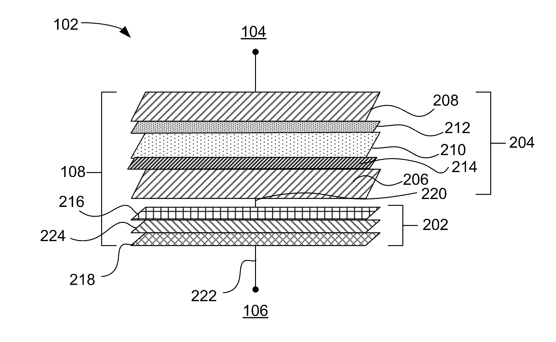
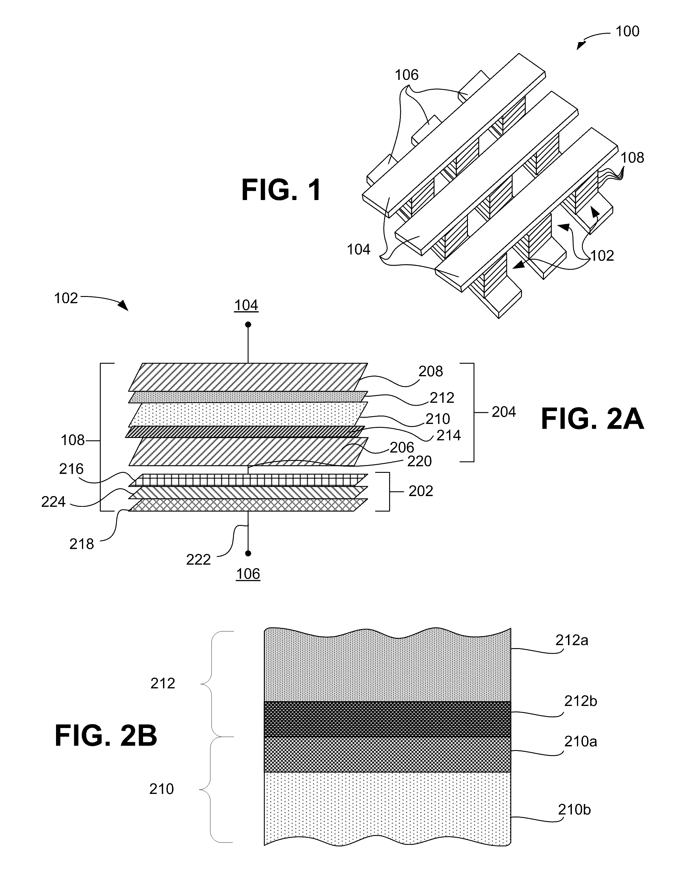
[0020]According to various embodiments, resistive-switching memory elements are described herein. The memory elements generally have a metal-insulator-metal (MIM) structure in...


PUM


Abstract

Resistive-switching memory elements having improved switching characteristics are described, including a memory element having a first electrode and a second electrode, a switching layer between the first electrode and the second electrode comprising hafnium oxide and having a first thickness, and a coupling layer between the switching layer and the second electrode, the coupling layer comprising a material including metal titanium and having a second thickness that is less than 25 percent of the first thickness.

Description

CROSS-REFERENCE TO RELATED APPLICATIONS[0001]This application is a continuation-in-part and claims the benefit of U.S. application Ser. No. 12 / 610,236 filed Oct. 30, 2009, and entitled “Resistive-Switching Memory Elements Having Improved Switching Characteristics”, which is incorporated by reference in its entirely for all purposes.FIELD OF THE INVENTION[0002]The present invention relates generally to semiconductor memories. More specifically, resistive-switching memory elements having improved switching characteristics are described.BACKGROUND OF THE INVENTION[0003]Non-volatile memories are semiconductor memories that retain their contents when unpowered. Non-volatile memories are used for storage in electronic devices such as digital cameras, cellular telephones, and music players, as well as in general computer systems, embedded systems and other electronic devices that require persistent storage. Non-volatile semiconductor memories can take the form of removable and portable mem...

Claims


Application Information

Patent Timeline
IPC IPC(8): H01L45/00H01L21/02
CPCH01L45/1616H01L45/1641H01L27/2409H01L45/146H01L45/08H01L45/1233H01L27/2481H10B63/20H10B63/84H10N70/245H10N70/25H10N70/841H10N70/883H10N70/023H10N70/041H10N70/826H10N70/8833
Inventor KUSE, RONALD JOHNHASHIM, IMRANCHIANG, TONY
Owner INTERMOLECULAR
Why Eureka
Try Eureka