Whistle
a technology of whistle and whistle, applied in the field of whistle, can solve the problems of blown frequency limitation, no large advancement in principle, and interruption of gam
- Summary
- Abstract
- Description
- Claims
- Application Information
AI Technical Summary
Benefits of technology
Problems solved by technology
Method used
Image
Examples
first embodiment
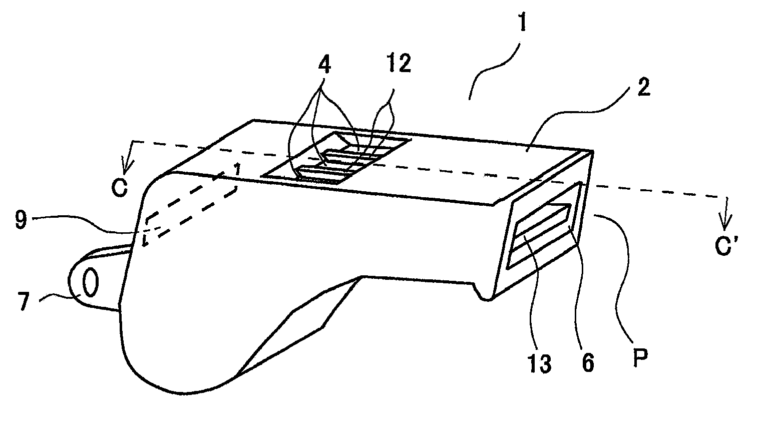
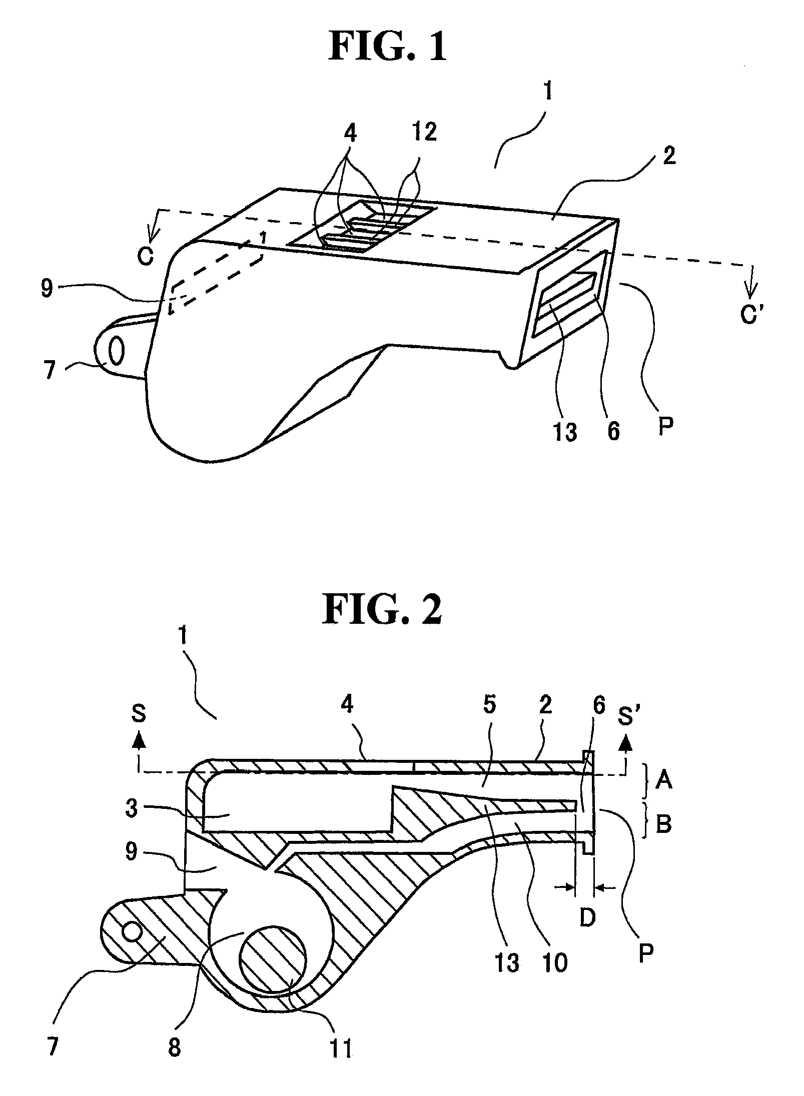
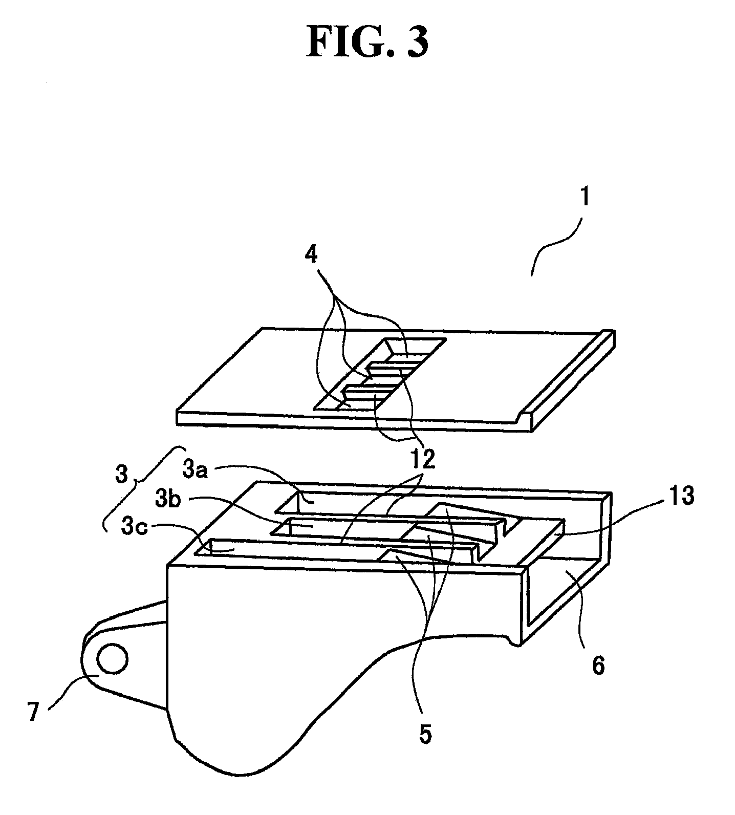
[0042]FIGS. 1 and 2 respectively show an external appearance of a simplest and basic whistle 1 of the present invention and a C-C′ cross section thereof. FIG. 3 draws an inner surface of an upper whistle A cut along an S-S′ surface in FIG. 2.
[0043]The whistle 1 of the first embodiment employs a two-layer structure that two independent first whistle A and second whistle B spaced apart by a partition wall 13 are stacked in the vertical direction and integrated together.
[0044]The first whistle A is a non-oscillator whistle comprising a first resonant chamber (upper resonant chamber) 3 which is a composite resonant chamber including rectangular tiny resonant chambers 3a, 3b, and 3c having different lengths spaced apart by respective partition walls first orifices 4 divided by respective partition walls 12 correspondingly to the respective tiny resonant chambers 3a, 3b, and 3c and opened upwardly, and a first air feeding tube 5. The respective lengths of the tiny resonant chambers 3a, 3...
second embodiment
[0051]Moreover, as is clear from FIG. 5, the orifices 4, 9 of both whistles are opened frontward, so that whistle sound is efficiently transmitted in a short time. The further characteristic point of the second embodiment is that an intersection angle α between a mouthpiece axis X and a resonant-chamber-body axis Y interconnecting the first resonant chamber 3 and the second resonant chamber 8 together is 30 to 75 degree, preferably, 50 to 70 degree. This allows formation of concave curved faces d, e between a resonant-chamber body 16 and the mouthpiece 2 as shown in FIG. 5. The shape thereof functions as a stopper which fits the lip of a person moderately, so that it is possible to stably put the mouthpiece 2 in a mouth. Accordingly, this is an efficient shape for sport referees who needs a rapid motion and cannot hold the whistle by a hand because of such a motion with both hands. It is apparent that this discriminative shape is realized by not only the two-layer structure of oscil...
fourth embodiment
[0055]FIG. 8 shows a fourth embodiment which further facilitates selection of tone. A part of the partition wall 13 is cut out, and is replaced with a rotatable air amount adjusting flap 20. FIG. 9 shows an X-X′ cross section thereof.
[0056]As shown in FIG. 8, the air amount adjusting flap 20 is connected to a shaft (cylinder) 21, and is a plate that a lower half part (surrounded by a dashed line) from the center of the shaft 21 is cut out, and the size thereof is slightly smaller than the first and second air feeding tubes 5, 10. The thickness thereof is substantially same as the wall thickness of a notched part of the partition wall 13. In the figure, a knob 22 is fixed to a left end of the shaft 21, and a compressed spring 23 is provided between the knob 22 and the mouthpiece 2. Accordingly, the knob 22, the shaft 21 connected thereto, and the air amount adjusting flap 20 are always pulled to the left in the figure relative to the mouthpiece 2. In the figure, the shaft 21 can be s...
PUM
 Abstract
Description
Claims
Application Information
 - R&D
- Intellectual Property
- Life Sciences
- Materials
- Tech Scout
- Unparalleled Data Quality
- Higher Quality Content
- 60% Fewer Hallucinations
Browse by: Latest US Patents, China's latest patents, Technical Efficacy Thesaurus, Application Domain, Technology Topic, Popular Technical Reports.
© 2025 PatSnap. All rights reserved.Legal|Privacy policy|Modern Slavery Act Transparency Statement|Sitemap|About US| Contact US: help@patsnap.com


