
Back brace

a back brace and back technology, applied in the field of back braces, can solve the problems of back braces being uncomfortable, the area surrounding the injection site sore, and the bar or the bar across the torso to be uncomfortabl

Inactive Publication Date: 2010-10-14
X BACK BRACING SERVICES
View PDF10 Cites 13 Cited by
  • Summary
  • Abstract
  • Description
  • Claims
  • Application Information

AI Technical Summary

Problems solved by technology

Patients generally find the bar or bars across their torso to be uncomfortable.
They also often find such back braces uncomfortable due to the lack of airflow to the portions of the body covered by the brace.
However, often patients are bruised in the spinal area or may receive injections adjacent the spine which may make the area surrounding the injection site sore.
Conventional back braces that apply pressure directly on the spine, therefore, may further irritate an already sore spinal area or may actually cause pain where there otherwise might be no pain by virtue of the pressure applied directly to the spine.
Conventional back braces also are generally rather complicated to fit and often require several visits to a physician in order to be correctly fitted to the patient.
Finally, conventional back braces are static in the sense that, once fitted and worn, the brace is rigid and does not adapt well to wearer movement.
In fact, a common occurrence with conventional static back braces is that, as the wearer flexes and moves about while performing his or her normal activities, the back-brace often loses contact with the back.
First, the back brace is not where it is supposed to be to properly support the desired portions of the back and hyperextend the spine.
Secondly, it can be rather uncomfortable when it rides up, especially for women.

Method used


Image

  • Back brace
  • Back brace
  • Back brace

Examples


Embodiment Construction

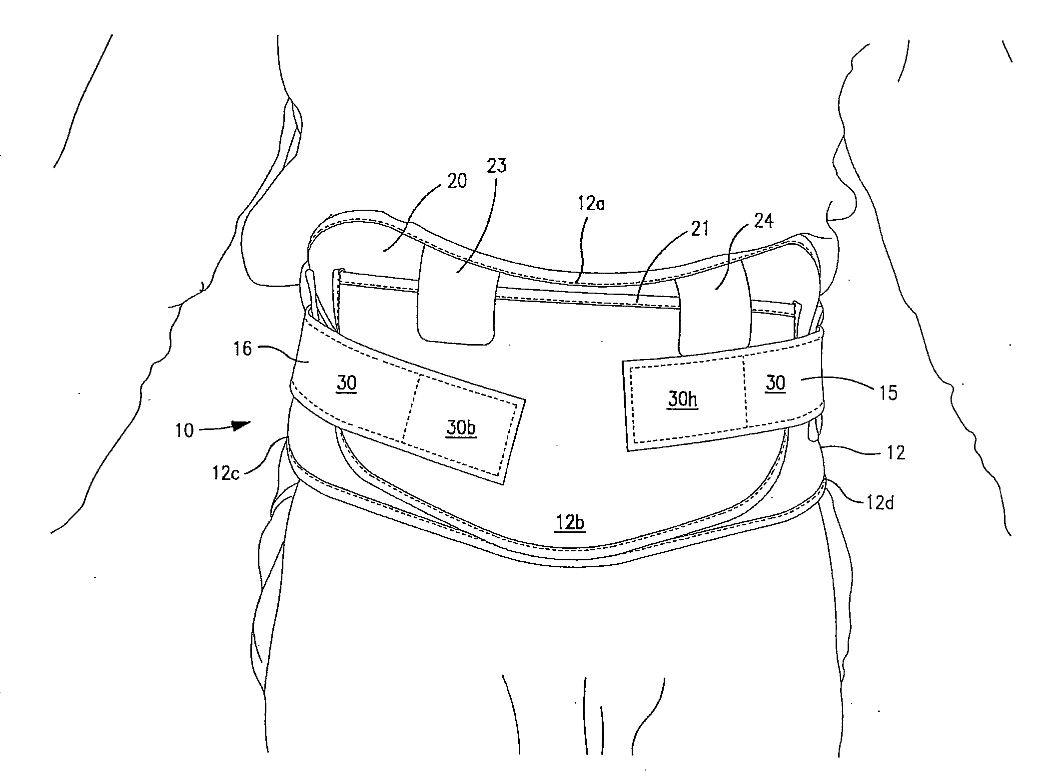
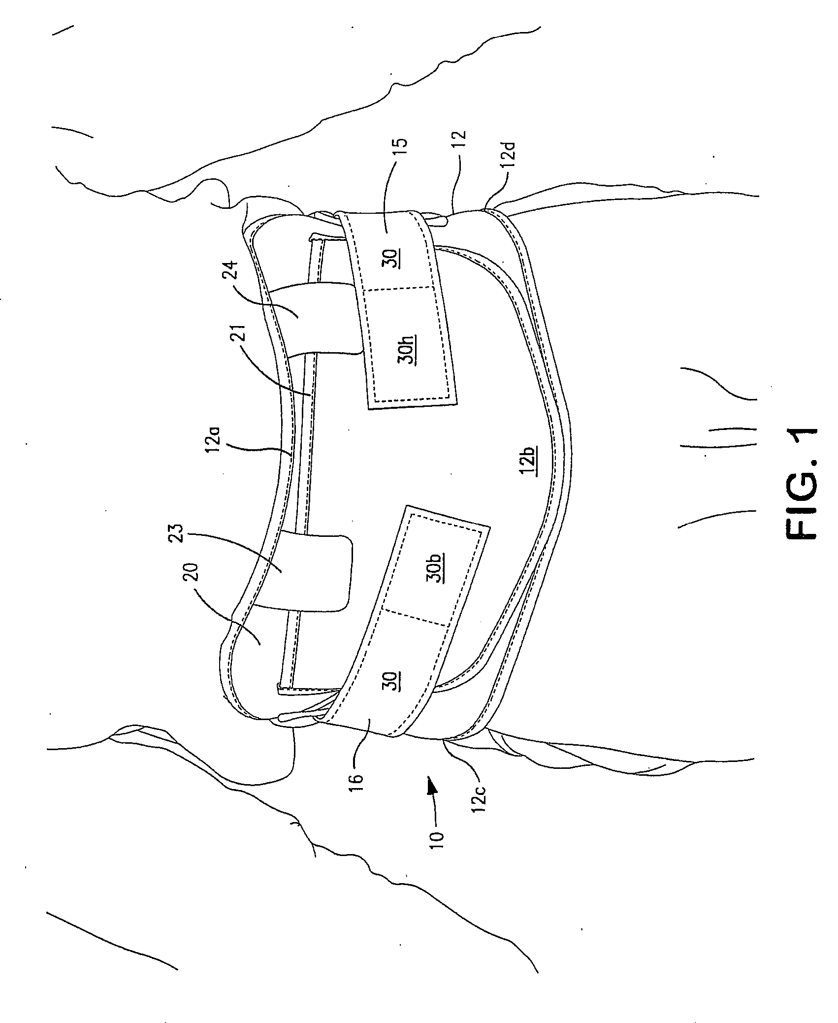
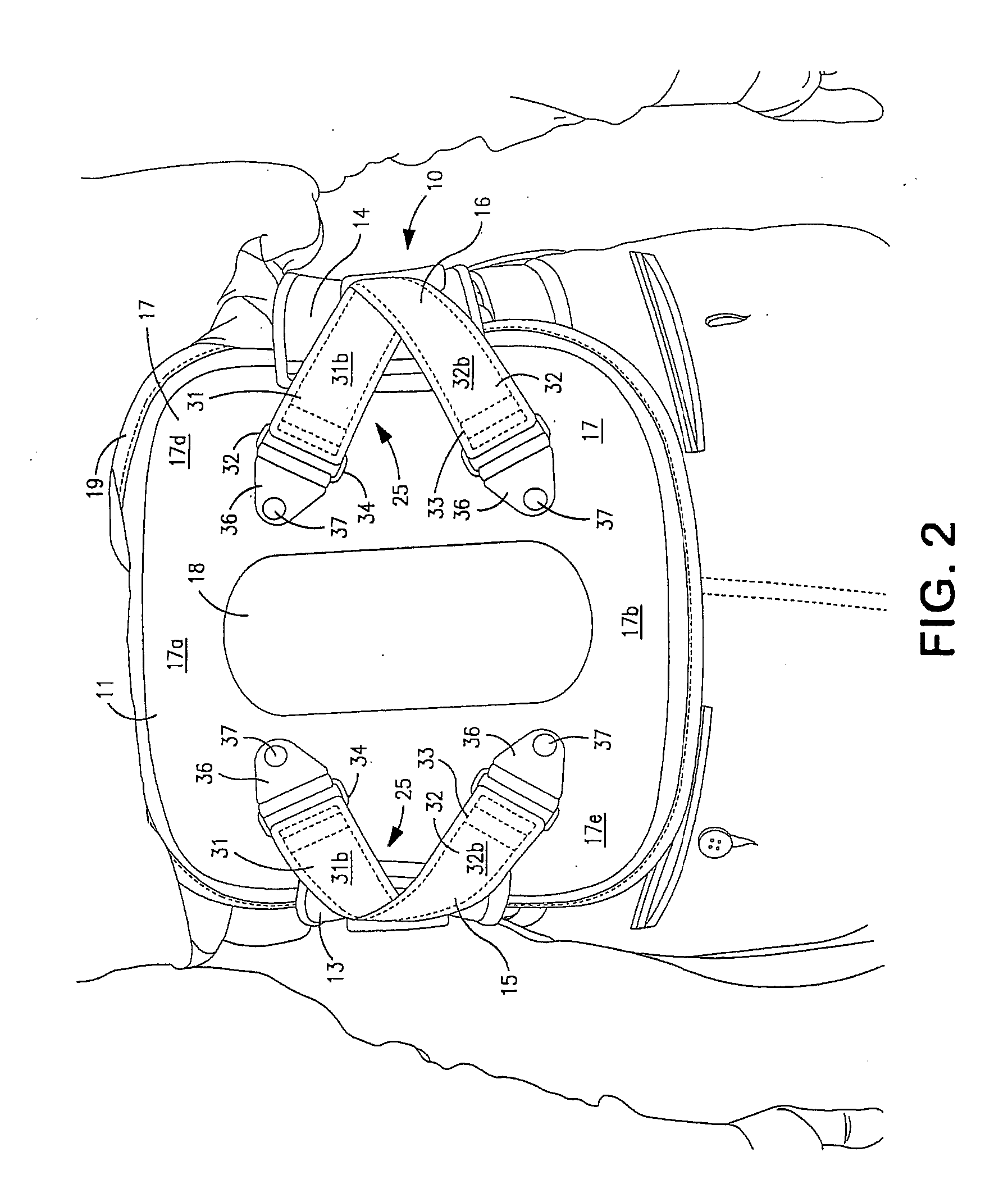
[0012]A back brace in accordance with one embodiment of the invention is a hyper-extension lumbar sacral orthotic (LSO) brace 10 providing trunk support extending from the sacral spine to the T-9 vertebrae. This is what is commonly called a standard LSO back brace. However, the invention can be incorporated into other size back braces, such as full size LSO back braces that provide trunk support extending from the sacral spine to the scapular plane or a TLSO back brace providing support from the sacral spine to the scapular plane. The back brace 10 comprises a back panel 11 for contacting the wearer's back, a front panel 12 for contacting the wearer's abdomen, two elastic straps 13, 14 (best seen in FIG. 3) for attaching the front panel 12 to the back panel 11 (as will be described in more detail below), and a dynamic force strapping system 25 comprising two additional strap assemblies 15, 16.

[0013]The use of the term “panel” with respect to front and back panels 12 and 11 is not in...


PUM


Abstract

The invention is a back brace including a back panel, a front panel, and at least one dynamic tension strap for connecting the front panel to the back panel.

Description

FIELD OF THE INVENTION [0001]The invention pertains to back braces. More particularly, the invention pertains to back braces for creating lift and support of the spine and abdomen.BACKGROUND OF THE INVENTION [0002]There are many medical conditions, including both post-surgical and non-post-surgical conditions, in which it is necessary for a patient to wear a back brace to assist creating lift and support of the spine. Such conditions include compression fractures, herniated discs, bulging discs, severe degenerative disc diseases that cause kyphosis, chronic and acute strain associated with lumbar instability, post-surgical kyphoplasty, mechanical back pain, scoliosis, spondylosis, spondylolisthesis, and post-surgical stabilization.[0003]Conventional back braces utilize one or more rigid bars that run vertically and / or horizontally across the wearer's torso to which is attached a lower back bracing pad that contacts the wearer's lower back.[0004]Patients generally find the bar or bar...

Claims


Application Information

Patent Timeline
IPC IPC(8): A61F5/00
CPCA61F5/028
Inventor LUSKY, STEVEN A.MARSHALL, TROY Q.
Owner X BACK BRACING SERVICES
Learn More