Cross arm hanging point load calculating method under fluctuating wind effect during transmission line windage yaw

A calculation method, technology of transmission lines, applied in the direction of spatial arrangement/configuration of cables, etc.

Inactive Publication Date: 2015-02-18
NORTH CHINA ELECTRIC POWER UNIV (BAODING) +1
View PDF3 Cites 11 Cited by
  • Summary
  • Abstract
  • Description
  • Claims
  • Application Information

AI Technical Summary

Problems solved by technology

In previous designs, the average wind load acting on the transmission line was often multiplied by a certain empirical coefficient, while the impact of fluctuating wind on the transmission line was ignored.

Method used


Image

  • Cross arm hanging point load calculating method under fluctuating wind effect during transmission line windage yaw
  • Cross arm hanging point load calculating method under fluctuating wind effect during transmission line windage yaw
  • Cross arm hanging point load calculating method under fluctuating wind effect during transmission line windage yaw

Examples


Embodiment

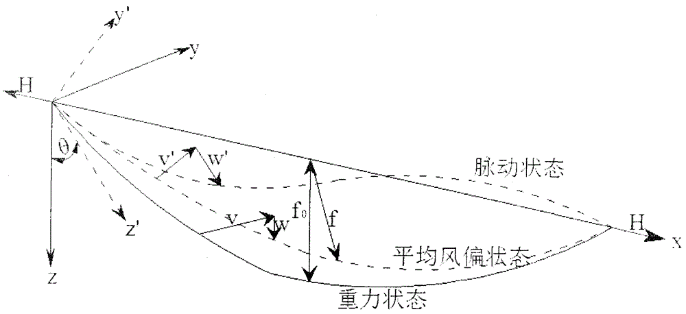
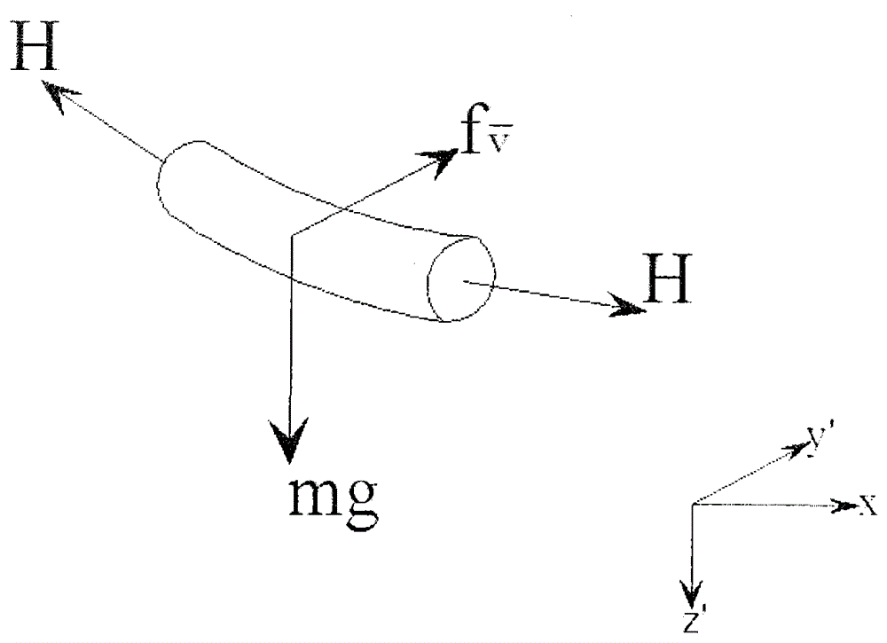
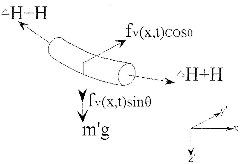
[0029] A method for calculating the load of the cross-arm hanging point when the transmission line is wind deflected under the action of fluctuating wind, comprising the following steps:

[0030] 1) Iteratively solve the chord tension H of the transmission line under the average wind deflection state:

[0031] H = EA 24 L 2 ( q 2 H 2 - ( mg ) 2 H 0 2 ) + H 0 - - - ( 1 )

[0032] Among them, m is the m...


PUM


Abstract

The invention discloses a cross arm hanging point load calculating method under the fluctuating wind effect during transmission line windage yaw. The method comprises the following steps: 1, solving the chordwise tension H of a power transmission line under the average windage yaw state through iteration; 2, solving the dynamic tension DH under the fluctuating wind effect; 3, solving the end tension of the power transmission line. By means of the Cross arm hanging point load calculating method under the fluctuating wind effect during transmission line windage yaw, the influence of the dynamic tension caused by fluctuating wind to the two ends of the power transmission line can be considered during tower structure load calculation in transmission tower design, and it is of great significance in enhancing the tower bearing capacity and ensuring safety operation of a power grid.

Description

technical field [0001] The invention relates to a method for calculating the load of a cross-arm hanging point when a transmission line is wind deflected, in particular to a method for calculating the load of a cross-arm hanging point when a transmission line is wind deflected under the action of fluctuating wind, and belongs to the technical field of transmission pole and tower design. Background technique [0002] Wind deflection of overhead transmission lines is a common phenomenon in the operation of transmission lines, and wind deflection tripping is a frequent cause of grid operation failures. Transmission lines are different from transmission lines. Under the action of strong wind, phase-to-phase swings are prone to occur. On the one hand, it will cause the distance between phases to decrease. After the deviation, it is easy to cause fatigue damage to insulators, hardware, and towers. However, the success rate of reclosing after wind deflection tripping is low. As a...

Claims


Application Information

Patent Timeline
Patent Type & Authority Applications(China)
IPC IPC(8): H02G7/20
CPCH02G7/20
Inventor 万书亭古祥科李永刚韩永强李龙隆玉福
Owner NORTH CHINA ELECTRIC POWER UNIV (BAODING)
Why Eureka
Try Eureka