
Pipe hanger

Inactive Publication Date: 2010-10-21
HALEXSCOTT FETZER
View PDF10 Cites 14 Cited by
  • Summary
  • Abstract
  • Description
  • Claims
  • Application Information

AI Technical Summary

Benefits of technology

[0010]One advantage of this invention is that pipe and other such objects can be easily suspended from support structures without the use of fasteners.
[0011]Another advantage of this invention is that a pipe hanger can be easily adjusted to support pipes, conduits, and the like of varying sizes.

Problems solved by technology

While known pipe hangers generally work well for their intended purposes, the use of fasteners may prove to be inconvenient and tedious.
Further, fasteners may damage the object being suspended or the suspending structure.

Method used


Image

  • Pipe hanger
  • Pipe hanger
  • Pipe hanger

Examples


Embodiment Construction

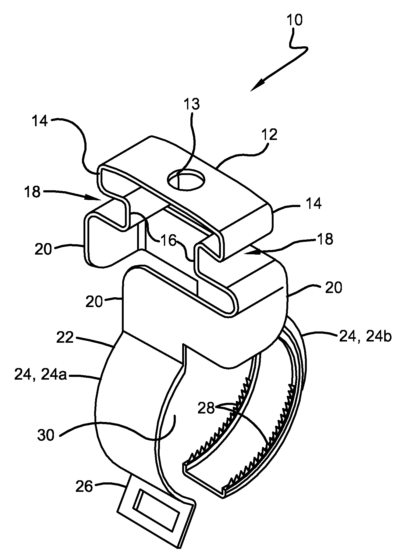
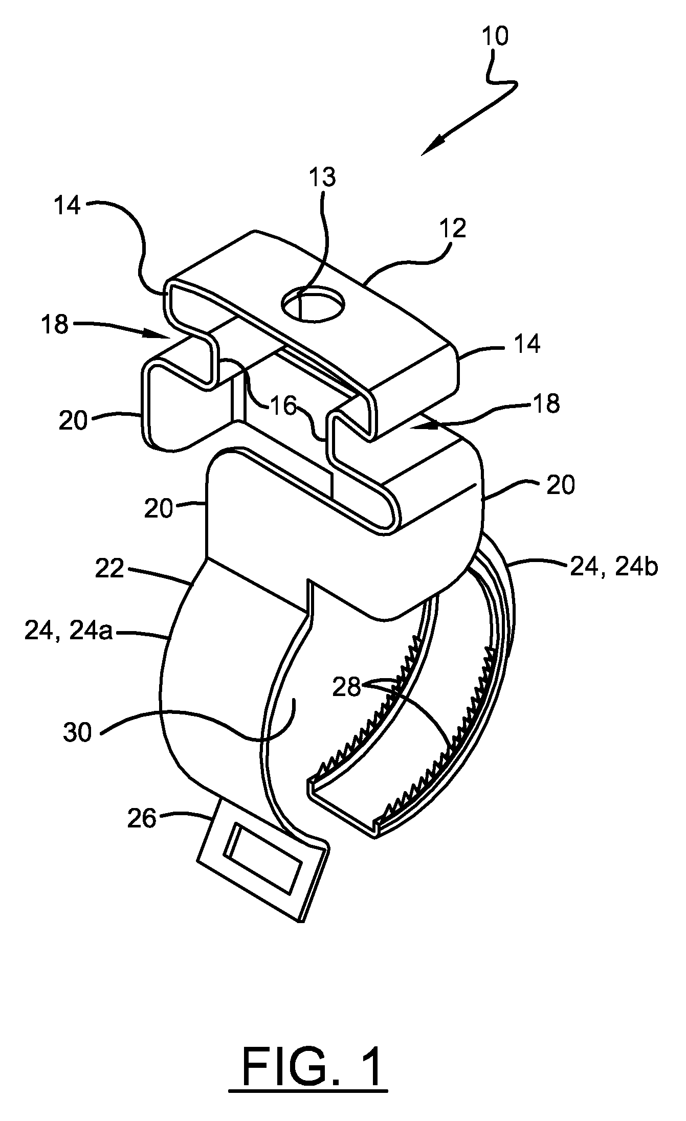
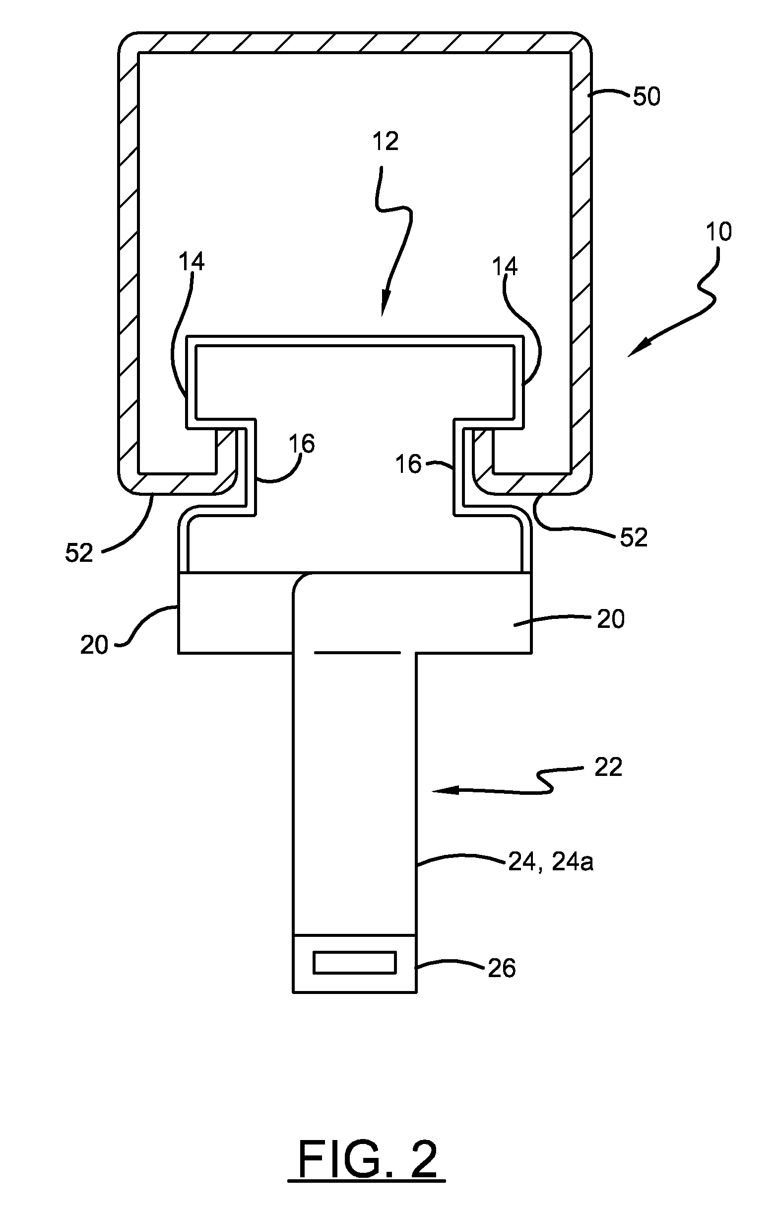
[0028]Referring now to the drawings wherein the showings are for purposes of illustrating embodiments of the invention only and not for purposes of limiting the same, and wherein like reference numerals are understood to refer to like components, FIG. 1 shows a pipe hanger 10 that generally comprises a suspending portion 12 and a retaining portion 22. Suspending portion 12 is generally formed and shaped for engaging a desired support structure from which pipe hanger 10 suspends. For example, the suspending portion 12 of FIG. 1 comprises an I-shaped cross-section for engaging a strut 50, or any other support structure 50, such as is shown in FIG. 2. It is also recognized that suspending portion 12 may form a T-shaped structure for use with the strut 50. Accordingly, suspending portion 12 may form any cross-sectional shape adapted for engaging a desired support structure 50, which may include without limitation a T-shaped or arbitrarily shaped cross-section. Suspending portion 12 may ...


PUM


Abstract

A pipe hanger may include a suspending portion with a body and two flanges that extend outwardly from the body and are positional onto projections of a support structure to suspend the pipe hanger from the support structure without the use of fasteners.

Description

[0001]This application claims priority to U.S. Ser. No. 61 / 169,056, entitled HANGER FOR CONDUIT AND THE LIKE, filed Apr. 14, 2009, which is incorporated herein by reference.I. BACKGROUND OF THE INVENTION[0002]A. Field of Invention[0003]The invention generally relates to methods and apparatuses concerning hangers used to support pipes, conduits, cables, and the like, to joists, rafters, trusses and other building structural support members of the like.[0004]B. Description of the Related Art[0005]Often, pipes, conduits, cables, wires, and similar objects extend along a structure, such as, for example, a ceiling, rafters, joists, beams, trusses, or struts, and are suspended or supported to such support structures with fasteners and / or straps. FIG. 11 shows a known pipe hanger 500 which includes a supporting surface 502 and a pair of arms 504 that extend from the supporting surface 502. A bolt or other fastener (not shown) is inserted through hole 506 formed in the supporting surface 50...

Claims


Application Information

Patent Timeline
IPC IPC(8): F16L3/08
CPCF16L3/133H02G3/32F16L3/24F16L3/2431
Inventor GARDNER, MICHAEL A.
Owner HALEXSCOTT FETZER
Learn More