Buck system

a buck system and buck technology, applied in the field of buck systems, can solve the problems of affecting the thermal performance of the wall and the attached component, cup, warp and/or twist, labor-intensive process,

Inactive Publication Date: 2010-10-28
BRILL GEROW D MR
View PDF77 Cites 14 Cited by
  • Summary
  • Abstract
  • Description
  • Claims
  • Application Information

AI Technical Summary

Benefits of technology

[0020]Any insulated concrete form (ICF) structure needs to accommodate windows, doors and other openings in the wall structure. Generally these are accomplished by a buck system. This application discloses an insulated buck system having a plurality of extruded channels; a plurality of foam panels; and a plurality of F-connectors. The foam panels are inserted within a pair of extruded channels to create planks. These pairs of extruded channels containing foam panels (planks) are coupled to each other by the F-connectors. The insulated buck system may include one or more bracing bracket(s) for temporary usage to provide rigidity during the installation of the insulated buck system.

Problems solved by technology

This procedure is labor intensive, time consuming and therefore quite costly.
However, this system requires the installation of a large number of web connectors and wedges before the wall can be poured.
The wooden construction of these conventional bucks results in a variety of problems because of the inherent qualities of wood.
This results in a common problem known in the construction field as buck shrinkage, which can affect the thermal performance of the wall and the attached component.
If the conventional buck frame members undergo buck shrinkage, they may cup, warp and / or twist.
This frequently results in cracks in the wall providing opportunities for air infiltration thereby compromising the thermal performance of the walls.
Moreover, the use of wooden framed bucks may lead to significant problems resulting from insect infestation.
Also, the wood frame has low thermal insulative properties, which is becoming an increasingly significant issue in modern construction.
While such an attachment method is feasible, it is often difficult to anchor fasteners within the hardened concrete of the building wall.
Moreover, the inherent dimensional instability and other detrimental qualities of wood, including those discussed above, can result in undependable alignment of the mounted component within the form wall system, as well as cracking of interior wall finishing, such as dry wall.
Moreover, the cost of constructing such wooden retainers in terms of material and labor is high, especially when constructing a large commercial building, or other structure with many wall openings.

Method used


Image

  • Buck system
  • Buck system
  • Buck system

Examples


Embodiment Construction

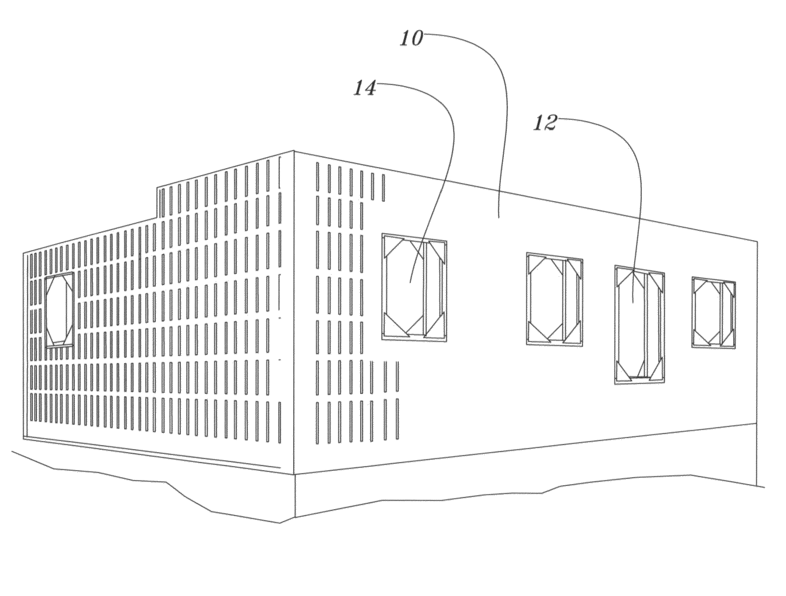
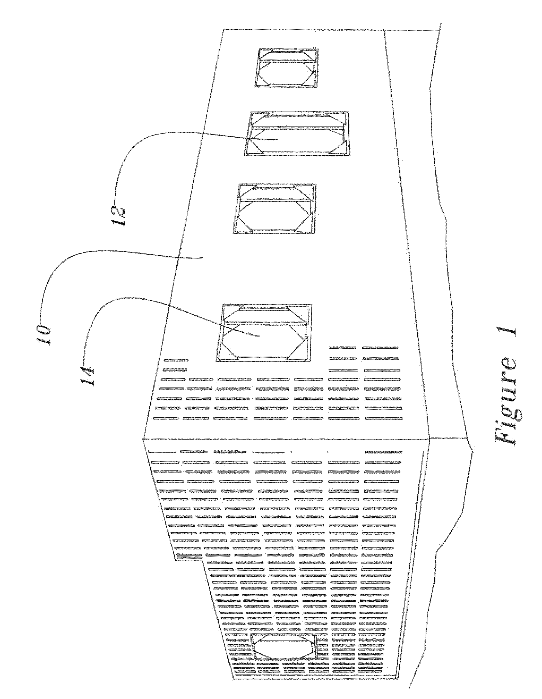
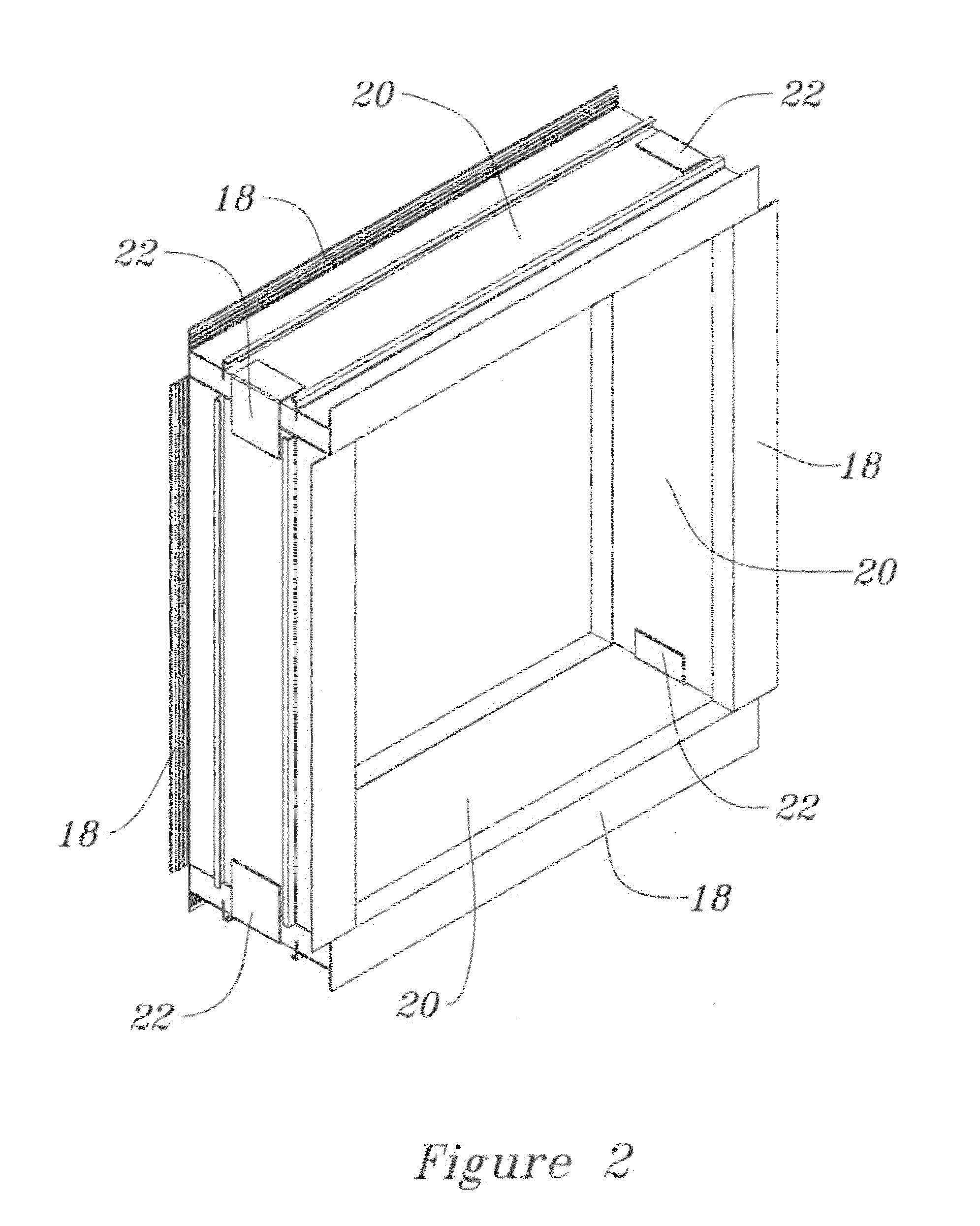
[0044]Herein we disclose an improved buck system for use with insulated concrete form (ICF) structures. FIG. 1 illustrates an insulated foam structure 10 with several insulated buck systems installed 12 and 14. FIG. 2 illustrates an isometric view of an insulated buck system 16. The system illustrated in FIG. 2 includes four pairs of extruded channels 18 each with a foam panel 20 supporting a pair of extruded channels 18. An F-shaped extruded connector couples two pairs of extruded channels with a foam panel 20 installed within the pair of extruded channels. Four pairs of extruded channels with their foam panels each pair coupled by an F shaped connector produces an insulated buck system.

[0045]In order to provide a stable rectangular shape, a triangular shaped corner bracing bracket is temporally installed in each corner of an insulated buck system as illustrated in FIG. 3.

[0046]Once the complete insulated buck systems and the other elements of the insulated concrete forms of the st...


PUM


Abstract

The invention discloses an insulated buck system for an insulated concrete form ICF) structure having a plurality of extruded channels, a plurality of foam panels; and a plurality of F-connectors wherein the foam panels are inserted within the extruded channels. Pairs of the extruded channels containing foam in between (planks) are coupled to each other by the F-connectors. The structure of the insulated buck system provides and an insulated seal for the window or door installed within the insulated buck system. Additionally mounting plates for mounting items to the insulated buck system are described. A triangular bracing bracket is also disclosed. A kit of parts is described.

Description

CROSS REFERENCE[0001]This application is related to Provisional Patent Application 61 / 189,666 filed on Aug. 21, 2008 entitled Buck System hereby incorporated herein by reference.FIELD OF INVENTION[0002]This disclosure describes an improved buck system for use within an integrated concrete form (ICF) structure.BACKGROUND OF THE INVENTION[0003]This disclosure discusses the use of buck systems within an ICF structures. Examples of an ICF structure include U.S. Pat. Nos. 6,079,176 and 6,351,918 by Westra et al. These patents disclose a system for insulating only the interior surface of a concrete wall to be poured between a pair of interior and exterior wall forms. The system includes horizontally extending elongated tie strips which connect to each of the wall forms to hold the wall forms spaced apart, a single layer of insulation positioned in contact with the interior wall form, and a plurality of connectors for securing the single layer of insulation to only the interior surface of ...

Claims


Application Information

Patent Timeline
Patent Type & Authority Applications(United States)
IPC IPC(8): E06B1/04E06B1/02E06B1/60
CPCE04G15/02E04B2002/8676
Inventor WESTRA, GREGORY
Owner BRILL GEROW D MR
Why Eureka
Try Eureka