Spring system for upholstery, mattresses or the like

a spring system and mattress technology, applied in the field of spring systems, can solve the problems of considerable restriction of the movement ability of the slat ends, and achieve the effects of reducing the interspace, preventing undesirable lateral movement or slipping of the mattress, and good bearing surfa

Inactive Publication Date: 2010-10-28
THOMAS HILFEN HILBEG
View PDF13 Cites 0 Cited by
  • Summary
  • Abstract
  • Description
  • Claims
  • Application Information

AI Technical Summary

Benefits of technology

[0014]The slats, preferably the slat ends, have arranged on them lateral guide elements which are designed such that a lateral movement of upholstery, mattresses or the like butting against the spring system is limited and / or prevented. There is therefore no need for any additional external frame in order to prevent undesirable lateral movement or slipping of the mattress or of the upholstery. Furthermore, provision may be made to fasten the upholstery, the mattress or the like directly on these lateral guide elements. The lateral guide elements expediently have guide surfaces which run perpendicularly to the slat plane and butt laterally against the mattress or the upholstery. The upholstery or the mattress is thus arranged between the lateral guide elements. It is advantageously possible to change the position of the lateral guide elements relative to the longitudinal slat direction, in which case either upholstery or mattresses of different widths can be used or a certain amount of lateral movement of the same may be permitted. The lateral guide elements may be formed by wing elements which can be tilted wholly or partially relative to the slat plane.
[0015]In a particular embodiment, a knitted fabric, in particular a three-dimensional knitted fabric, may be positioned on the slats and is connected thereto preferably by a snap-in connection, in particular clamping or clip profiles. Such a knitted fabric can effectively reduce the interspaces between the individual slats in order to provide, for example, upholstery with a good bearing surface without it being necessary for the individual slats to be placed in position with narrower spacings.

Problems solved by technology

This type of support results in the slat ends being secured in spatial terms, but at least in the movement capability of the slat ends being restricted to a considerable extent.

Method used


Image

  • Spring system for upholstery, mattresses or the like
  • Spring system for upholstery, mattresses or the like
  • Spring system for upholstery, mattresses or the like

Examples


Embodiment Construction

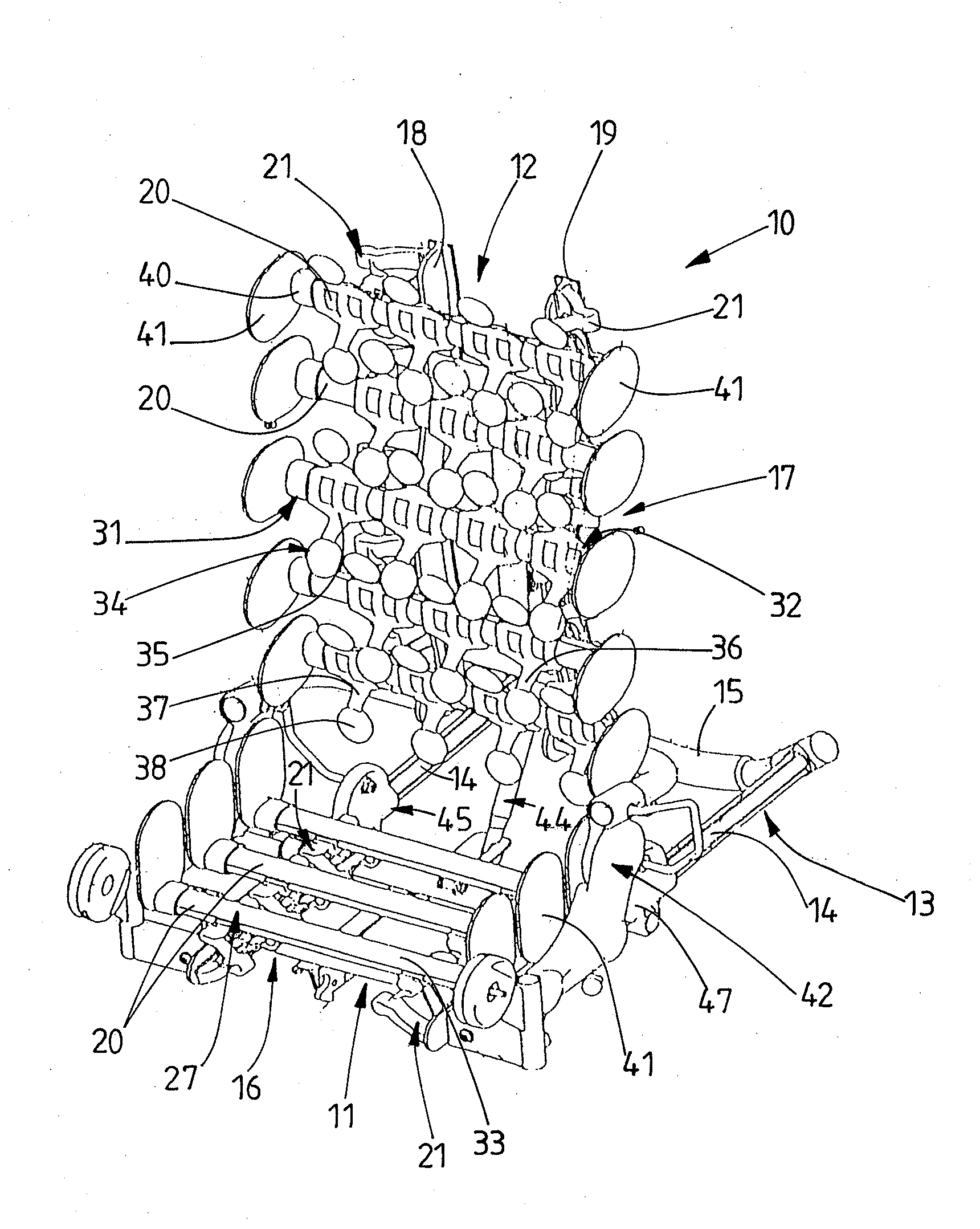
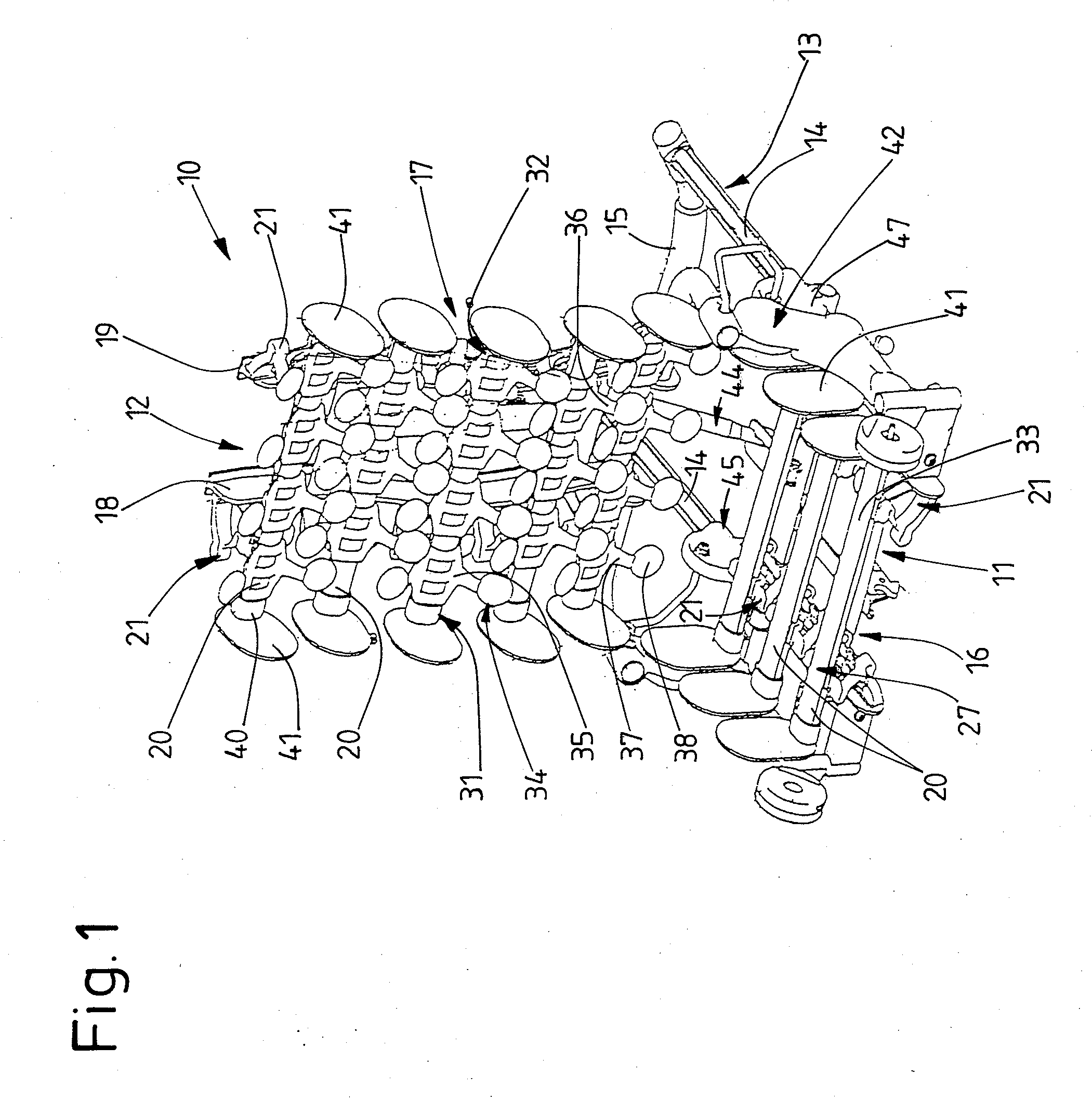
[0022]The spring system according to the invention will be explained with reference to a push-carriage seat 10, which may be part of a stroller or of a means of transporting disabled children or young people. The use of the spring system, of course, is not restricted to push-carriage seats. It may be used, for example, as a spring system for mattresses of a bed and as a spring system for upholstered furniture or the like.

[0023]The push-carriage seat 10 is fastened in a releasable manner on a chassis (not illustrated). The seat 10 here has a horizontal seat surface 11 and a backrest 12 which runs at an angle to the seat surface and can be adjusted in inclination in relation to the seat surface 11. The seat surface 11 and backrest 12 form a common structure which is mounted such that it can be displaced, in a manner which will not be explained in specific detail, on a substructure 13 made of two parallel guide rails 14 and a crossmember 15 which connects the rails at their ends.

[0024]...


PUM


Abstract

A spring system in particular for upholstery and/or mattresses of push-carriage seats, furniture for sitting on or lying on or the like, having a plurality of successively spaced-apart slats (20), in particular resilient slats, and having supporting bodies (21) for supporting the slats directly or indirectly on a carrying structure. The bearing points or bearing regions (27) of the slats (20), in which the slats (20) are supported by the supporting bodies (21), are arranged exclusively between the slat ends (31, 32).

Description

STATEMENT OF RELATED APPLICATIONS[0001]This application is the U.S. National Phase Under Chapter II of the Patent Cooperation Treaty (PCT) of PCT International Application No. PCT / EP2006 / 008006 having an International Filing Date of 12 Aug. 2006, which claims priority on German Patent Application Nos. 10 2005 039 432.9 having a filing date of 18 Aug. 2005 and 10 2006 031 999.0 having a filing date of 11 Jul. 2006.BACKGROUND OF THE INVENTION[0002]1. Technical Field[0003]The invention relates to a spring system, in particular for upholstery and / or mattresses of push-carriage seats, furniture for sitting on or lying on or the like, having a plurality of successively spaced-apart slats, in particular resilient slats, and having supporting bodies for supporting the slats directly or indirectly on a carrying structure.[0004]2. Related Art[0005]Push-carriage seats and furniture for sitting on or lying on usually have a spring system comprising a so-called slatted base. The slatted base of ...

Claims


Application Information

Patent Timeline
Patent Type & Authority Applications(United States)
IPC IPC(8): F16F3/00B60N2/70A47C7/28A47C23/12
CPCA47C7/028A47C23/064A47C7/28A47C7/40
Inventor JANSEN, KLAUS
Owner THOMAS HILFEN HILBEG
Why Eureka
Try Eureka