Dimmable light generating device

a light generating device and fluorescent lamp technology, applied in the field of fluorescent lamps, can solve the problems of color deviation and technique requiring amplitude modulation means, and achieve the effects of constant heating of electrodes, simple means of implementation, and constant color of light emitted

Inactive Publication Date: 2010-10-28
KONINKLIJKE PHILIPS ELECTRONICS NV
View PDF3 Cites 7 Cited by
  • Summary
  • Abstract
  • Description
  • Claims
  • Application Information

AI Technical Summary

Benefits of technology

[0014]It is a specific objective of the present invention to provide a dimming method and apparatus capable of providing dimming over a large range, using relatively simple means of implementation, and yielding a substantially constant color of the light emitted.
[0015]It is a further specific object of the present invention to provide an apparatus for dimming a lamp, provided with relatively simple means enabling substantially constant heating of the electrodes, independent of the dimming level.

Problems solved by technology

One disadvantage of this known technique is that, over a large dimming range, current of less than nominal value is used, resulting in a deviation of the color.
Further, a disadvantage is that this known technique requires amplitude modulation means.

Method used


Image

  • Dimmable light generating device
  • Dimmable light generating device
  • Dimmable light generating device

Examples


Embodiment Construction

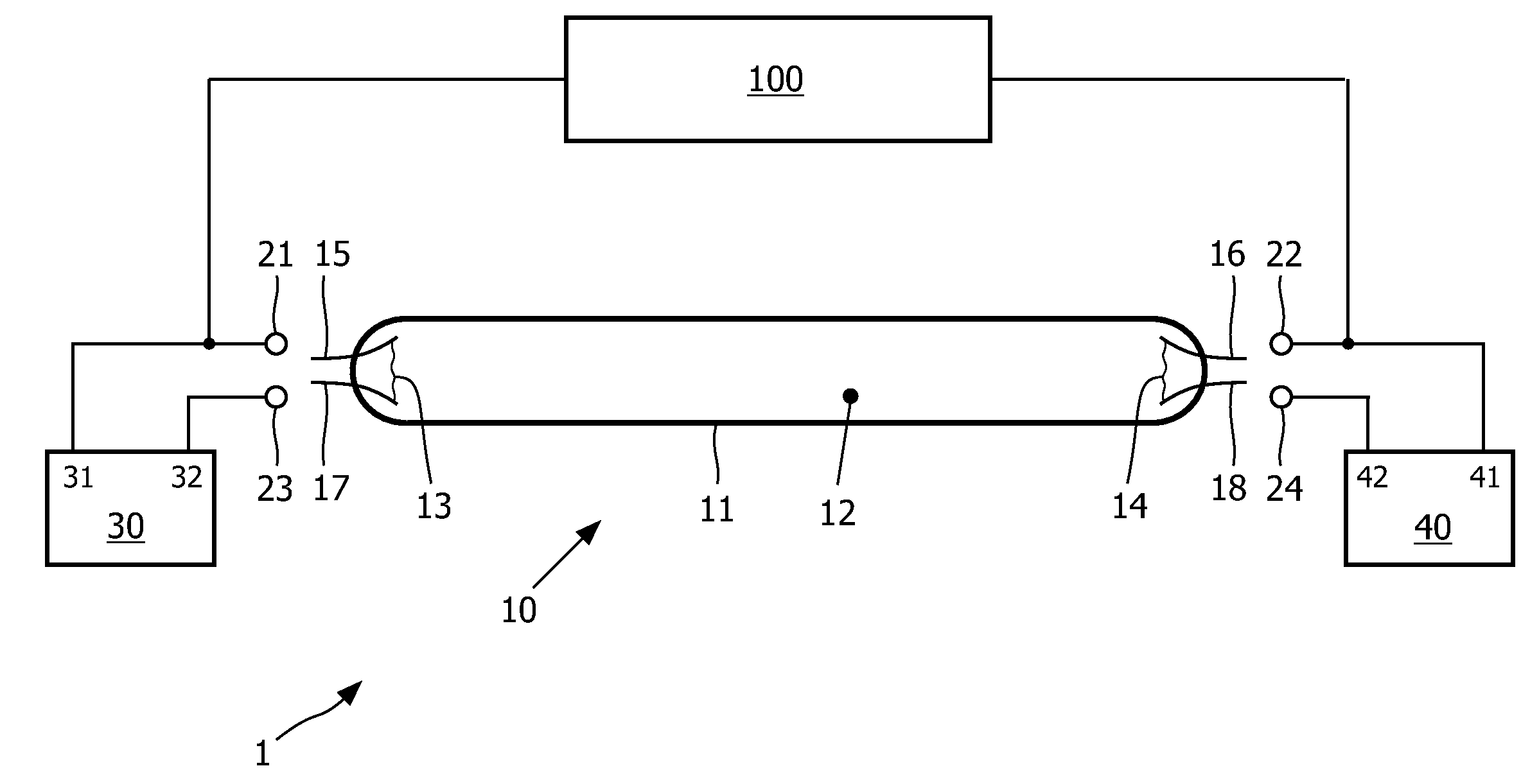
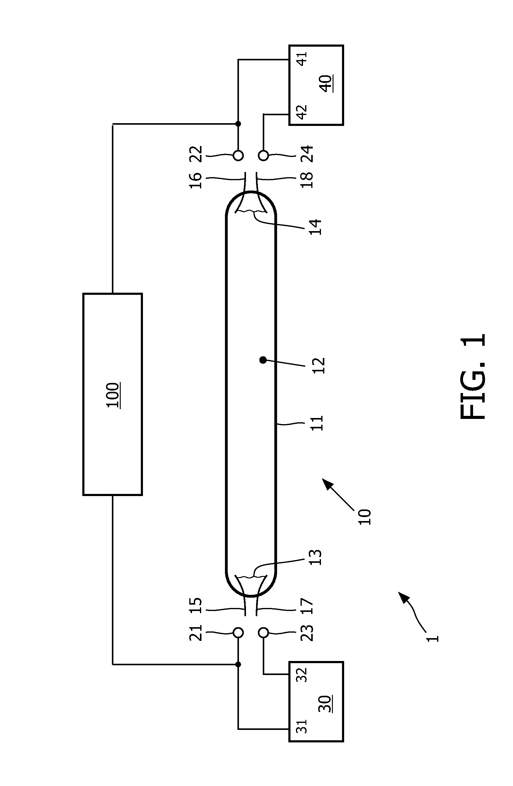
[0029]FIG. 1 is a block diagram schematically illustrating some features of an electronic driver 1 for driving a gas discharge lamp 10. The lamp 10 is a hot cathode fluorescent lamp, and comprises a lamp tube 11 having an interior space 12 and two electrode filaments 13, 14 arranged within the interior space 12, indicated as first and second electrode filaments 13, 14, respectively. Each electrode filament is provided with two electrode terminals 15, 17 and 16, 18, respectively, extending to the exterior beyond the lamp tube 11.

[0030]The driver 1 has output terminals 21, 22, 23, 24 connected to the lamp electrode terminals 15, 16, 17, 18, respectively. Particularly, a first output terminal 21 is connected to a first electrode terminal 15 of the first lamp electrode filament 13, a second output terminal 22 is connected to a first electrode terminal 16 of the second lamp electrode filament 14, a third output terminal 23 is connected to a second electrode terminal 17 of the first lamp ...


PUM


Abstract

A wake-up lighting device is described, comprising a gas discharge lamp (10) and a lamp driver (1; 2) comprising a power source (100) capable of generating spaced-apart current bursts (51) of alternating lamp current (I). The wake-up lighting device is capable of operating in an off-mode in which no lamp current is generated, and is adapted to switch from its off-mode to a wake-up mode in which the power source (100) operates to:—initially generate an alternating lamp current (I) with a minimum duty cycle value (ΔT) and a reduced current amplitude (IR) close to zero;—subsequently gradually increase the current amplitude while keeping the duty cycle (Δ) constant at the minimum duty cycle value (ΔT), until the current amplitude reaches a nominal current amplitude (IM);—subsequently gradually increase the duty cycle (Δ) while keeping the current amplitude constant at the nominal current amplitude (IM).

Description

FIELD OF THE INVENTION[0001]The present invention relates in general to the field of fluorescent lamps, more particularly a dimmable light generating device comprising a fluorescent lamp.BACKGROUND OF THE INVENTION[0002]There is a general tendency to replace the traditional incandescent lamps by other types of light sources, such as LEDs and gas discharge lamps. LEDs and gas discharge lamps have, with respect to each other, some advantages and disadvantages, and a designer may choose to use either an LED or a gas discharge lamp, depending on his design considerations.[0003]A light source, be it an incandescent lamp, an LED or a gas discharge lamp, is designed for nominal operation with a nominal lamp voltage and a nominal lamp current, resulting in a nominal lamp power and a nominal light output. If, in a certain situation, a user wishes to have more light, he may replace the current lamp by a more powerful lamp, or by a lamp of a different type having a higher light output. Convers...

Claims


Application Information

Patent Timeline
Patent Type & Authority Applications(United States)
IPC IPC(8): H05B41/36
CPCH05B41/3921H05B41/295
Inventor DIJKSTRA, JACOBETTES, WILHELMUSHEERINGA, SCHELTEBREMER, PETRUS JOHANNES
Owner KONINKLIJKE PHILIPS ELECTRONICS NV
Why Eureka
Try Eureka