Vehicle positioning measurement system and method

a technology for positioning measurement and vehicles, applied in distance measurement, instruments, and reradiation, etc., to achieve the effect of improving road safety

Active Publication Date: 2010-10-28
SIGNIFY HLDG BV
View PDF13 Cites 29 Cited by
  • Summary
  • Abstract
  • Description
  • Claims
  • Application Information

AI Technical Summary

Benefits of technology

[0009]In an embodiment, the vehicle comprises the at least two light sources, the object comprises the at least one detector, and the detector is arranged to obtain the comparison phase from the light received from one of the light sources. Advantageously, this embodiment allows the object to obtain information about its environment. In an embodiment the object is another car, allowing for communicating vehicles with a 360 degree field of view. Advantageously, this improves road safety.
[0010]In an embodiment the light sources are arranged to transmit data in addition to the light source identification codes. In an embodiment the data comprises the predetermined distance between the light sources. Advantageously, this allows performing trigonimetrical calculations to determine not only the distance but also the position of the vehicle and object.

Problems solved by technology

Furthermore, the inventive system allows position / distance measurements with the vehicle rear and side marker lighting as well, since international standards do not allow these light sources to be adjustably mounted on vehicles.

Method used


Image

  • Vehicle positioning measurement system and method
  • Vehicle positioning measurement system and method
  • Vehicle positioning measurement system and method

Examples


Embodiment Construction

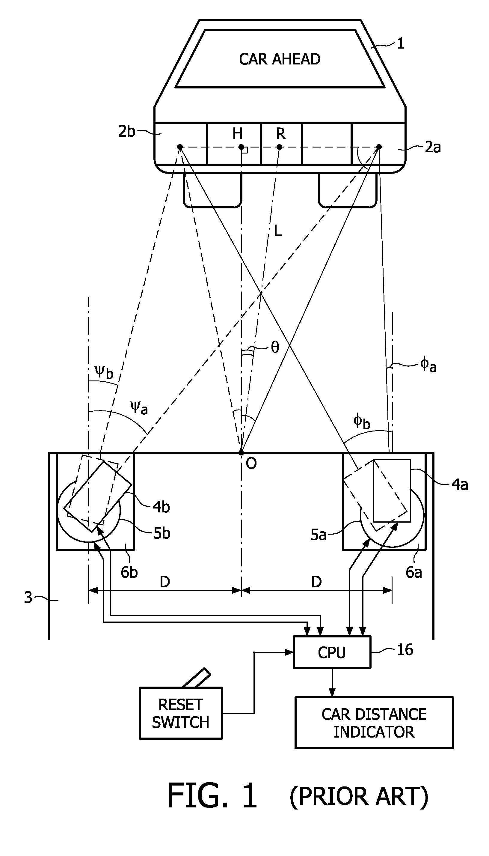
[0019]FIG. 1 shows a prior art car 3 to car 1 distance measurement system comprising two head lamps 6a,b each including an optical device 4a,b. The headlamps 6a,b are installed at a distance 2D from each other. The optical devices include a light projector (not shown) for projecting coded light and a light receiver (not shown) for detecting the reflected light from the car 1 ahead. The optical devices 4a,b can be rotatably driven by respective driving systems 5a,b. The light emitted from the headlamps 6a,b reflects from reflectors 2a,b provided on car 1 towards the receivers in the optical devices 4a,b, when the receivers driving systems 5a,b are at the angles Φa, Φb, Ψa, and Ψb. Detecting these angles using CPU 16 allows the determination of the position of the two cars, i.e. the distance L between the cars and the angle θ between the lines RO and HO perpendicular to car 3.

[0020]It is clear that the rotatably driven optical devices 4a,b in combination with the driving systems 5a,b ...


PUM


Abstract

A vehicle position measurement system (100) and method to determine the (relative) position of a vehicle (110) and an object (120) are proposed. The system comprises at least two light sources (131, 132) capable of emitting light and positioned at a predetermined distance (140) to each other. Furthermore the system comprises at least one detector (150/151, 152) capable of measuring the light emitted. The light emitted by the light sources comprises synchronized light source identification codes. The detector is arranged to determine the position of the vehicle (110) and object (120) on the basis of a phase-difference measurement between the light originating from the individual light sources (131, 132) and a comparison phase. The vehicle (110) may comprise the at least two light sources (131, 132) and the detector (151, 152), while the phase-difference is measured between light reflected from the object (120) and the comparison phase. Alternatively, the vehicle (110) may comprise the at least two light sources (131, 132) while the object (120) comprises the detector (150) and the detector is arranged to obtain the comparison phase from the light received from one of the light sources (131, 132). The object may be a vehicle.

Description

FIELD OF THE INVENTION[0001]The invention relates to a vehicle positioning measurement system according to the preamble of claim 1. The invention also relates to a vehicle position measurement method according to the preamble of claim 11. Such vehicle positioning measurement systems and methods are used in particular in situations where the determination of the (relative) position and / or distance between a vehicle and an object is desired. Examples of such situations are vehicle-to-vehicle distance measurement or localisation of objects as assistance during parking.BACKGROUND OF THE INVENTION[0002]U.S. Pat. No. 5,039,217 discloses a car-to-car distance measurement system in which one of the cars comprises a pair of headlamps disposed at a predetermined distance from each other. Each headlamp comprises an optical device having a light projector which projects pulse light having a specific code toward the car in front. Furthermore, the optical device comprises a light receiver capable...

Claims


Application Information

Patent Timeline
Patent Type & Authority Applications(United States)
IPC IPC(8): G01S5/16G01C3/08H04J14/00H04B10/04G01S17/931
CPCG01S11/12G01S17/936G01S17/36G01S17/931
Inventor DAMINK, PAULUS H.A.COLAK, SEL B.RONDA, CORNELIS R.FERI, LORENZOSCHENK, TIM C.W.
Owner SIGNIFY HLDG BV
Why Eureka
Try Eureka