Device and System for Display of Information, and Vehicle Equipped with Such a System

a technology for information displays and vehicles, applied in the direction of optical viewing, optical instruments, optics, etc., can solve the problems of obstructing the view of the driver, obstructing the view, and affecting the safety of drivers, so as to achieve simple and inexpensive head-up displays and improve road safety

Inactive Publication Date: 2007-12-13
TRYGGIT
View PDF5 Cites 11 Cited by
  • Summary
  • Abstract
  • Description
  • Claims
  • Application Information

AI Technical Summary

Benefits of technology

[0007] An object of the invention is to provide a simple and inexpensive “head-up display” allowing a more satisfactory positioning of the virtual image, inter alia to improve road safety.

Problems solved by technology

At the same time, almost all the available space of the driver's cab of a typical commercial vehicle is taken up by various devices and equipment, which makes it difficult to find a place to display the information.
Providing a large, continuous display surface in front of the driver is impossible, since it would be partly concealed by the steering wheel, it would obstruct the view and distract the driver.
When the real image, as shown in WO 89 / 03059, is created obliquely below and in front of the driver, it is difficult, impossible even, to avoid the virtual image being created somewhere in the active field of vision used by the driver to survey the traffic situation.
Nevertheless, the virtual image may still interfere with the driver's view.
Moreover, the transparent reflecting surface is such that the quality of the information displayed will be low, and only simple visual indications can be displayed.
However, it is apparent from said specification that it is both time-consuming and expensive to provide a device featuring a long optical path, which can also be contained in an instrument panel.

Method used


Image

  • Device and System for Display of Information, and Vehicle Equipped with Such a System
  • Device and System for Display of Information, and Vehicle Equipped with Such a System
  • Device and System for Display of Information, and Vehicle Equipped with Such a System

Examples


Embodiment Construction

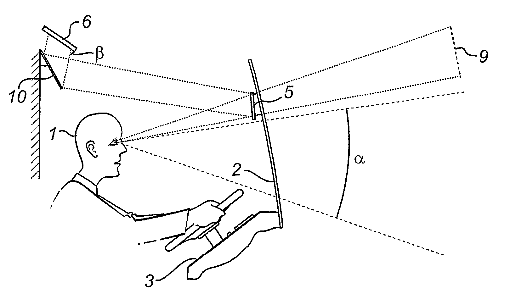
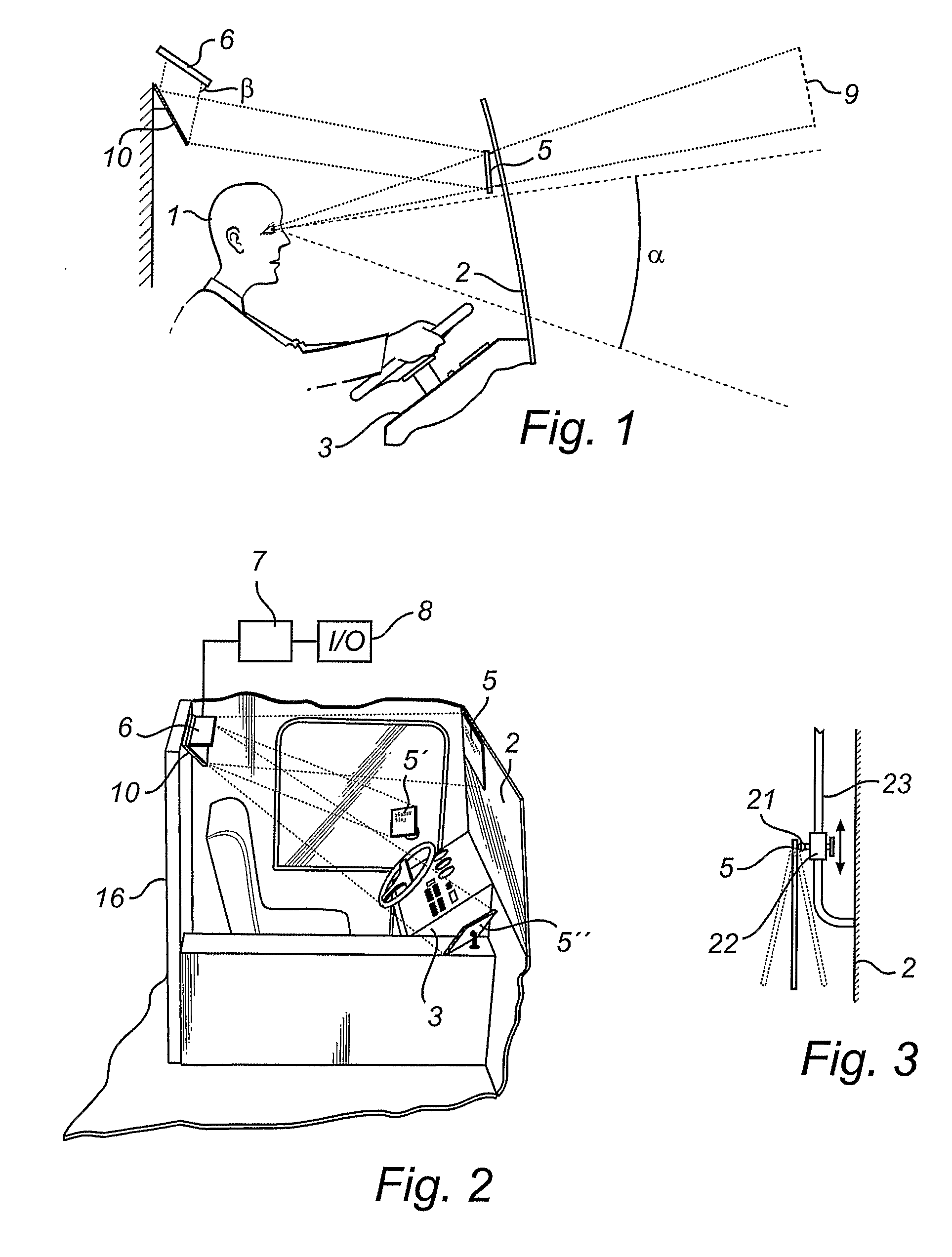
[0032]FIG. 1 shows a driver's cab in a commercial vehicle, here a bus, in which a driver 1 is positioned behind an essentially vertical windscreen 2 and an essentially horizontal instrument panel 3. The driver's active field of vision, i.e. the angular area α used by the driver during normal driving, typically ranges from about 2 degrees (the driver is looking more or less straight ahead) to about −25 degrees (the driver is looking at the roadway in front of the bus). A reflecting surface 5 is provided directly above the active field of vision α. The surface can be transmissive, for example by coating the windscreen with a translucent, reflective layer, or non-transmissive, i.e. a mirror. This reflecting surface 5, which in the following will be referred to as viewing surface, may extend across essentially the whole width of the windscreen, but may also have a more limited extension.

[0033] As shown in FIGS. 1-2, the viewing surface can also be located in the plane of the windscreen...


PUM


Abstract

A device is disclosed for displaying information in a vehicle. The device includes a unit for creating a real image containing information relevant to a driver, to be reflected in a reflective viewing surface located directly above the field of vision actively used by the driver to survey the traffic situation, and thereby generating a virtual image. The device further includes a second reflecting surface provided behind or beside the driver's head, with the driver in his or her normal position, at essentially the same level as the viewing surface or higher, an end section of an optical path between the unit and the viewing surface in use extending between said second reflecting surface and the viewing surface. By the optical path extending at least partly in the upper part of the driver's cab, a relatively long (several meters) optical path can be obtained without the need for complex mirror systems. In particular, this applies to commercial vehicles such as lorries and buses, which generally have an essentially vertical windscreen and plenty of free space above and in front of the driver.

Description

FIELD OF THE INVENTION [0001] The present invention relates to an improved and safer working environment for the driver of a vehicle. More specifically, the invention concerns a device for displaying information comprising a unit for creating a real image containing information relevant to the a driver, to be displayed in a reflecting viewing surface located directly above the field of vision actively used by the driver to survey the traffic situation, and thereby generating a virtual image by reflecting the real image. The invention further relates to a system comprising such a device, and a vehicle equipped with such a system. BACKGROUND ART [0002] In the working environment of a modern vehicle an ever-increasing amount of information can be made accessible to the driver. At the same time, almost all the available space of the driver's cab of a typical commercial vehicle is taken up by various devices and equipment, which makes it difficult to find a place to display the informati...

Claims


Application Information

Patent Timeline
Patent Type & Authority Applications(United States)
IPC IPC(8): G02B27/01B60R1/00G02BG02B27/00
CPCB60R1/00B60R2300/105B60R2300/205G02B2027/0161G02B27/0101G02B2027/0123B60R2300/207
Inventor BRYNIELSSON, THORE
Owner TRYGGIT
Why Eureka
Try Eureka