Method for machining an attachment flange of an aircraft turbomachine case

Active Publication Date: 2018-05-10
SN DETUDE & DE CONSTR DE MOTEURS DAVIATION S N E C M A
View PDF1 Cites 0 Cited by
  • Summary
  • Abstract
  • Description
  • Claims
  • Application Information

AI Technical Summary

Benefits of technology

The invention is a machine that can follow the shape of a flange and machine it without removing too much material. This results in a more cost-effective process. The machine uses a flexible module that can adjust to any geometrical defects on the flange. The machine also has a non-return mechanism to keep it in place and a support device to hold it steady as it moves along the flange. This invention helps to make precise cuts and reduces waste, which lowers manufacturing costs.

Problems solved by technology

However, the flange provided on the rough part to be machined is not always perfectly plane, since it does not have to be for correct assembly of the case on the adjacent turbomachine element.
On the other hand, these planeness defects of the flange can create fabrication problems, since due to these defects, the quantity of material to be removed is not the same along the entire surface of the flange.
These oversizes obviously have an impact on the initial global mass and production costs, and increase the quantity of material to be removed from the rough part by machining.
If there is not sufficient oversizing, there is a risk that the two plane surface grindings of the flange will cause one or several defective zones along the circumferential direction of the flange, zones in which the thickness of carbon is no longer sufficient to maintain satisfactory mechanical strength, and / or in which the glass coating is missing or is not sufficient to confer good galvanic protection.
Moreover, it is noted that the problem presented above occurs not only when the two opposite surfaces of the attachment flange are plane, but also when the flange is slightly inclined relative to a transverse plane of the case, leading to opposite surfaces in the form of truncated cones.

Method used


Image

  • Method for machining an attachment flange of an aircraft turbomachine case
  • Method for machining an attachment flange of an aircraft turbomachine case
  • Method for machining an attachment flange of an aircraft turbomachine case

Examples


Embodiment Construction

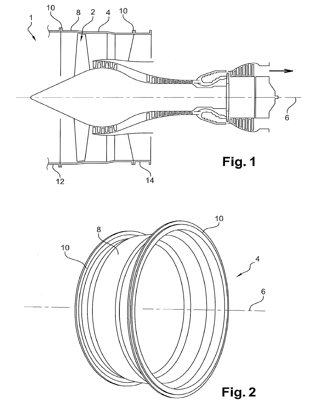
[0051]With reference firstly to FIG. 1, the figure shows an aircraft turbomachine 1, of the twin-spool turbojet type. This turbojet 1 is equipped with a fan 2 surrounded by fan case 4, centred on the longitudinal axis 6 of the turbojet. In a known manner, the fan case 4 comprises a shell 8 supporting two attachment flanges 10 at its ends. These flanges are used for mechanical connection with adjacent elements of the turbojet, normally an air intake12 and an external shell 14 of an intermediate case.

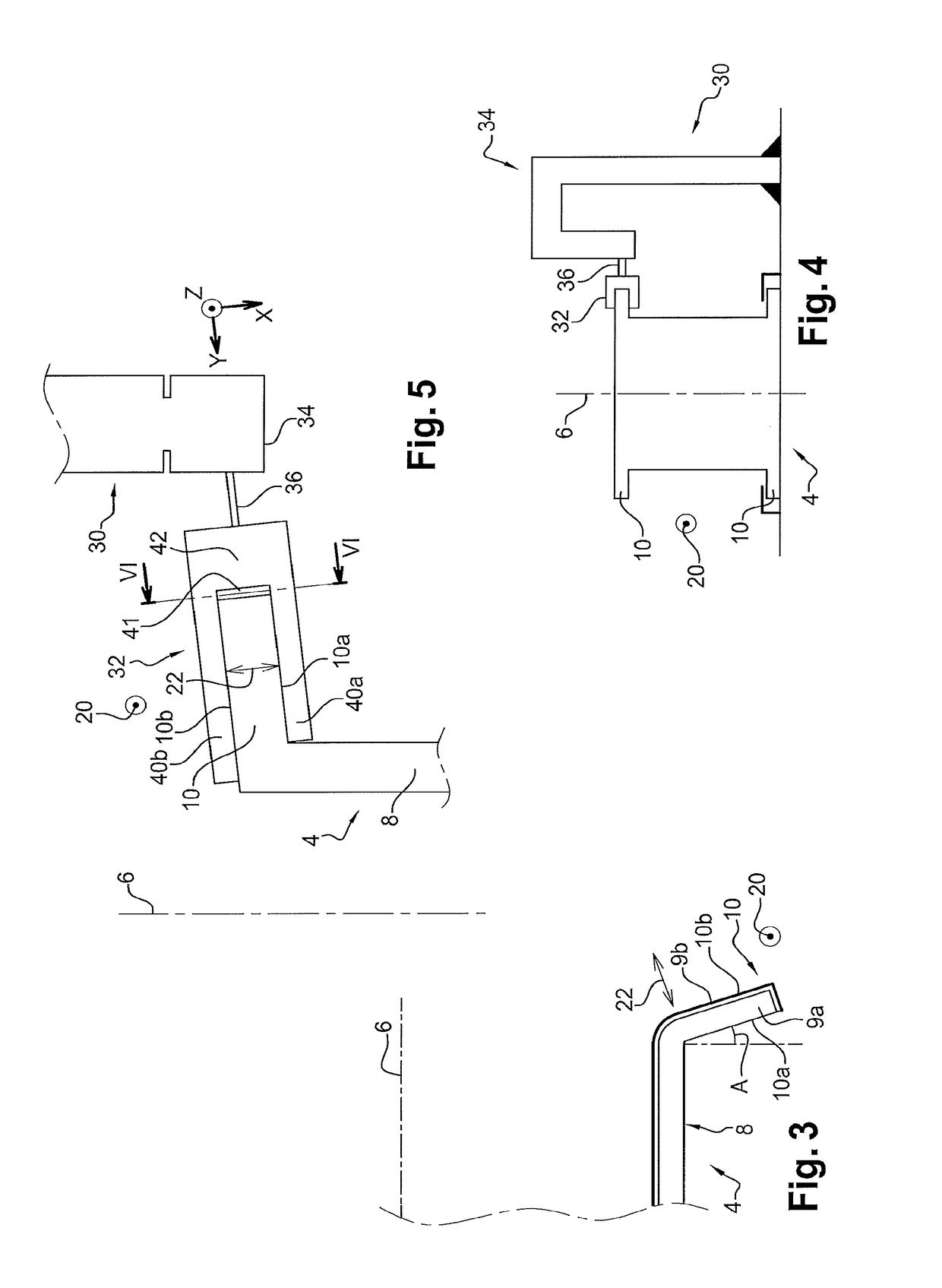
[0052]With reference to FIGS. 2 and 3, it can be seen that the two attachment flanges 10 extend essentially in the radially outwards direction from the shell 8. The flanges 10 can be inscribed in the transverse planes of the case 4, or they can be in the form of a truncated cone as shown diagrammatically on FIG. 3. In this case, there is an angle A between the normal to the shell 8 and the attachment flange, as seen in an axial half-section. This angle is normally small, for example a few...


PUM


Abstract

A method of machining an attachment flange of an aircraft turbomachine case, the method also including a system to machine the two opposite surfaces of the flange, and including a shape follower machining module, this module being designed to follow the shape of the flange and including a first structure equipped with a first machining tool, and a second structure equipped with a second machining tool, the flange fitting between the structures such that its two opposite surfaces are machined by tools, the module also including shape follower elements carried by the structures; and a device to drive movement of the machining module along a circumferential direction of the flange.

Description

TECHNICAL DOMAIN[0001]This invention relates to the domain of aircraft turbomachines, and more particularly to manufacturing of their cases, such as the fan case. It more specifically concerns the operation to machine a case flange.STATE OF PRIOR ART[0002]Normally, a turbomachine case comprises a shell at the ends of which there are two attachment flanges, for the mechanical connection of this case to other elements of the turbomachine.[0003]A case flange extends essentially radially outwards, from the shell of the same case. It may include a principal part made of carbon coated with a galvanic protection layer, for example obtained using a stack of several glass layers. The principal part made of carbon assures that the flange has good mechanical strength.[0004]After the rough case part has been obtained, different operations are usually carried out on the attachment flange, such as trimming, surface grinding and drilling holes through which attachment bolts can pass.[0005]Surface ...

Claims


Application Information

Patent Timeline
IPC IPC(8): B23C3/12B23Q35/10B23Q35/26F01D25/24
CPCB23C3/12B23Q35/104B23Q35/26F01D25/243F05D2230/10F05D2230/53F05D2240/14B23C2215/04B23C2220/40B23C1/16B23C3/00B23Q35/28
Inventor MOST, VINCENT BERNARD SERGEFABRE, HUBERT JEAN MARIE
Owner SN DETUDE & DE CONSTR DE MOTEURS DAVIATION S N E C M A
Why Eureka
Try Eureka