
Boiling water nuclear reactor and emergency core cooling system of the same

a nuclear reactor and core cooling technology, applied in nuclear engineering, nuclear elements, greenhouse gas reduction, etc., can solve the problems of molten core, damage to core, and falling water level in the pressure vessel of the reactor,

Active Publication Date: 2010-10-28
KK TOSHIBA
View PDF9 Cites 14 Cited by
  • Summary
  • Abstract
  • Description
  • Claims
  • Application Information

AI Technical Summary

Problems solved by technology

When a loss-of-coolant accident (LOCA) occurs and the pipe connected to the reactor pressure vessel is ruptured in the inside of the dry well, the water level in the reactor pressure vessel falls.
On the other hand, when the isolation valve and / or the pressure-reducing valve of the gravity-driven water injection pipe become unopenable for some reason or another, there arises a situation where the core can no longer be cooled.
Then, the core can become damaged and molten.
Besides a LOCA, an anticipated transient without scram (ATWS) can take place to threaten the safety of nuclear reactor.
This is an incident where the attempt to insert the control rods fails partly or totally although a scram is required for the nuclear reactor in order to protect the core and the reactor containment vessel when an accident of total loss of water feed to the nuclear reactor or an incident of a total closure of the main steam isolation valve occurs.
In such a situation, there arises a possibility that the injection of boric acid aqueous solution has been completed before the injection of water by means of the gravity-driven ECCS is started to make it difficult to maintain the subcritical state so that the core may be plunged back into a critical state because the boric acid is diluted by about 1,500 m3 cold water injected by the gravity-driven ECCS.

Method used


Image

  • Boiling water nuclear reactor and emergency core cooling system of the same
  • Boiling water nuclear reactor and emergency core cooling system of the same
  • Boiling water nuclear reactor and emergency core cooling system of the same

Examples


first embodiment

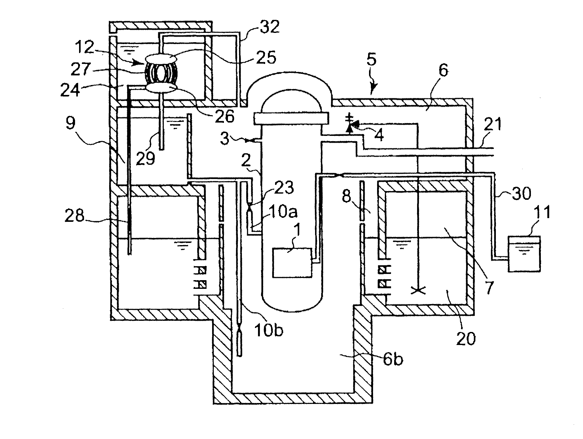
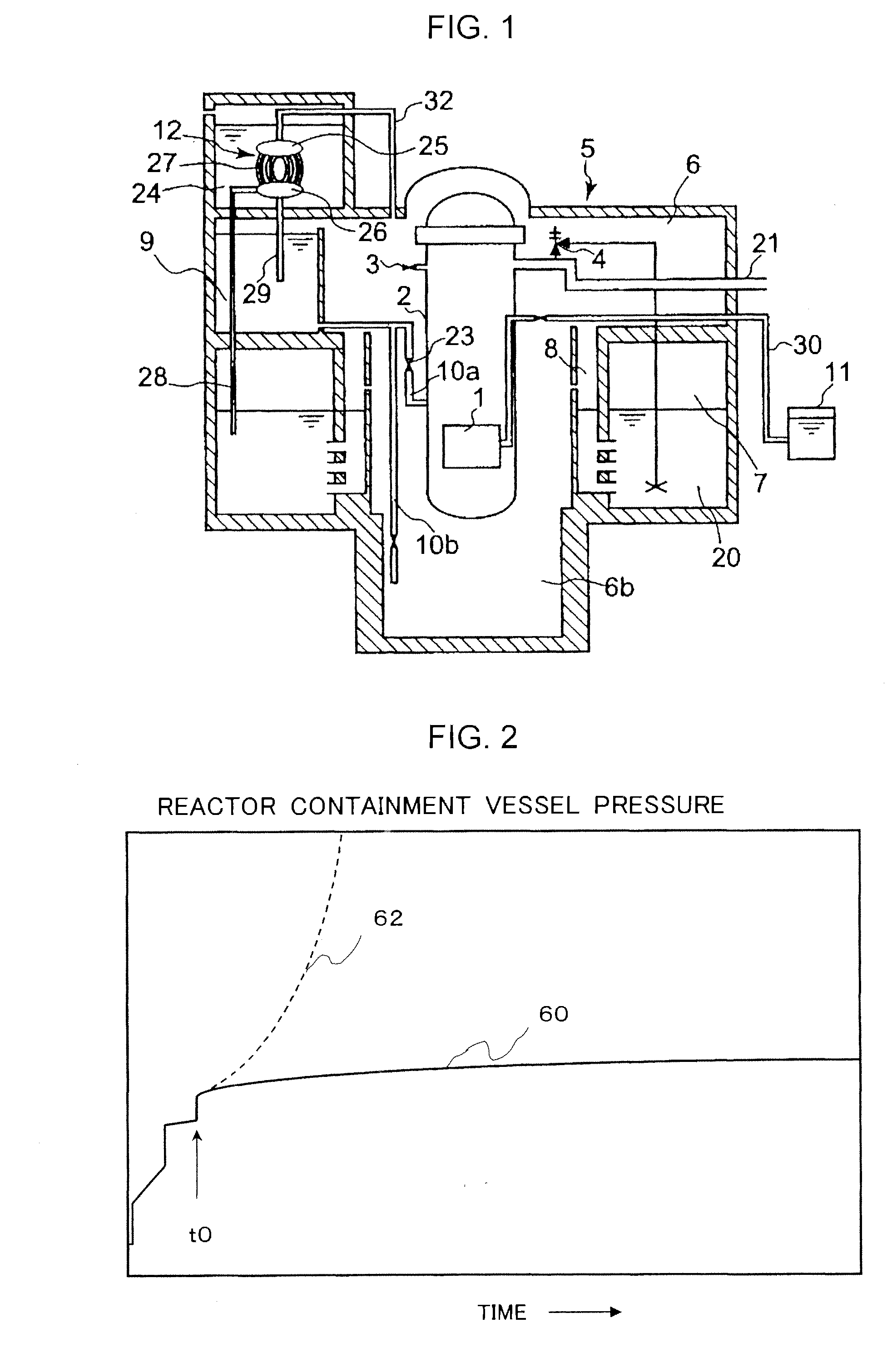
[0024]FIG. 1 is a schematic elevational cross-sectional view of the first embodiment of a boiling water nuclear reactor according to the present invention. The reactor containment vessel 5 of the reactor includes a dry well 6 and a wet well 7, and a reactor pressure vessel 2 of the reactor is contained in the dry well 6. A pressure suppression pool 20 is arranged in the wet well 7. The water in the pressure suppression pool 20 is used to fill the fuel exchange pool with water when the operation of the reactor stopped to replace the core fuel. The reactor pressure vessel 2 contains the core 1, the internal structure and the reactor water (not shown).

[0025]Vent pipes 8 extend from an upper part of the dry well 6 into the pressure suppression pool 20. Main steam pipes 21 are arranged to feed the main steam generated in the reactor pressure vessel 2 to the steam turbine (not shown) outside the reactor containment vessel 5 and main steam safety relief valves 4 are fitted to the main stea...

second embodiment

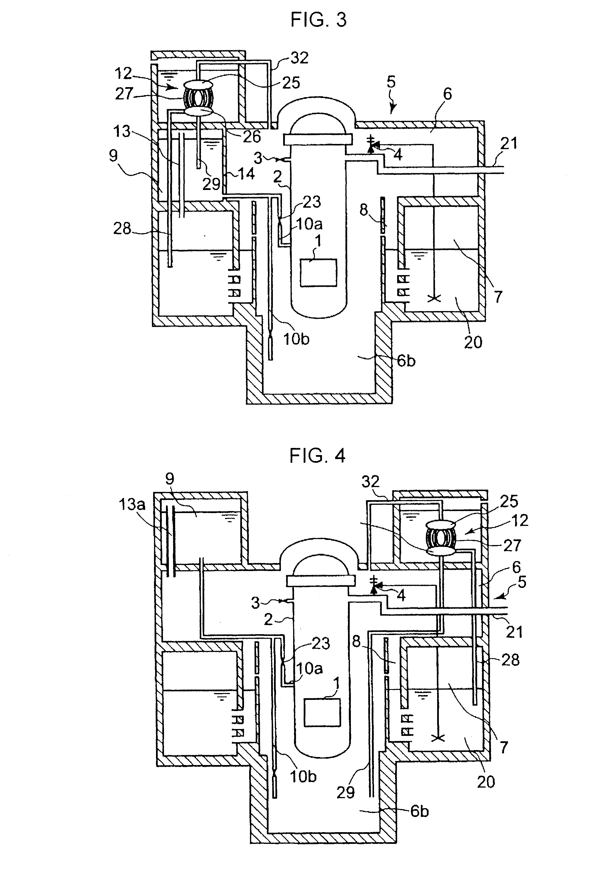
[0045]FIG. 3 is a schematic elevational cross-sectional view of the second embodiment of a boiling water nuclear reactor according to the present invention. In this embodiment, the gravity-driven water injection pool 9 holding boric acid aqueous solution is isolated from the dry well 6 by means of a partition wall 14. The gas phase section above the liquid surface of the gravity-driven water injection pool 9 is held in communication with the upper gas phase section in the wet well 7 by way of a first communication pipe 13.

[0046]The boric acid aqueous solution injection system including a boric acid aqueous solution injection tank 11 and a boric acid aqueous solution injection pipe 30 similar to its counterpart illustrated FIG. 1 are omitted in the embodiment shown in FIG. 3. However, the boric acid aqueous injection system may be arranged in this embodiment as in FIG. 1. This statement also applies to all the succeeding embodiments.

[0047]This embodiment operates like the first embod...

third embodiment

[0048]FIG. 4 is a schematic elevational cross-sectional view of the third embodiment of a boiling water nuclear reactor according to the present invention. In this embodiment, the gravity-driven water injection pool 9 holding boric acid aqueous solution is arranged above the ceiling of the reactor containment vessel 5. The gas phase section above the liquid surface of the gravity-driven water injection pool 9 is held in communication with an upper part of the dry well 6 by way of a second communication pipe 13a. Additionally, the drain pipe 29 connected to the bottom of the lower header 26 of the static containment vessel cooling system heat exchanger 12 extends down into the dry well lower region 6b in this embodiment.

[0049]This embodiment operates like the first embodiment in the sense that it can maintain the core in a subcritical state by holding boric acid aqueous solution in gravity-driven water injection pool 9. Additionally, the design limitations of the inside of the reacto...


PUM


Abstract

A boiling water nuclear reactor comprises: a reactor containment vessel including a dry well and a wet well; a vent pipe connecting the dry well and the pressure suppression pool; a gravity-driven water injection pool to hold boric acid aqueous solution; an emergency core water-injection piping system for causing the boric acid aqueous solution in the gravity-driven water injection pool to fall so as to be injected into the reactor pressure vessel in case of reactor accident; a static containment vessel cooling system pool; a static containment vessel cooling system heat exchanger; a dry well connection pipe connecting an upper part of the static containment vessel cooling system heat exchanger and the dry well; and a gas vent pipe for discharging noncondensible gas in the static containment vessel cooling system heat exchanger into the inside of the pressure suppression pool.

Description

CROSS REFERENCES TO RELATED APPLICATIONS[0001]The present application is a Divisional of U.S. application Ser. No. 12 / 056,813, filed Mar. 27, 2008 which is based upon and claims benefit of priority from prior Japanese Patent Application No. 2007-87617, filed in the Japanese Patent Office on Mar. 29, 2007, the entire content of which is incorporated herein by reference.BACKGROUND OF THE INVENTION[0002]This invention relates to a gravity-driven emergency core cooling system (ECCS) and also to a boiling water nuclear reactor (BWR) using the same.[0003]Studies are being made of introducing equipment that operates statically (passively), utilizing natural force, without using dynamic (actively) devices such as pumps mainly in order to raise the simplicity of safety equipment and improve the reliability of boiling water nuclear reactors. Among others, gravity-driven emergency core cooling systems (ECCS) are known for pouring water into the nuclear reactor in case of an accident as shown i...

Claims


Application Information

Patent Timeline
Patent Type & Authority Applications(United States)
IPC IPC(8): G21C9/00G21C9/004
CPCG21C9/004Y02E30/31G21C15/18Y02E30/30
Inventor KOJIMA, YOSHIHIROSATO, TAKASHIOIKAWA, HIROHIDE
Owner KK TOSHIBA
Learn More