Probe frame of supersonic inspection device for weld joint at safe end of nuclear reactor pressure vessel

A technology for ultrasonic inspection of pressure vessels, which is applied in the field of ultrasonic probe holders, can solve problems such as limitations, increased time for ultrasonic inspection of weld seams at the safety end of pressure vessels, and missing scans, and achieve accurate and reliable results, prevent scratches on the inner wall of the nozzle, and achieve good results. coupling effect

Active Publication Date: 2010-12-15
CGNPC INSPECTION TECH +2
View PDF4 Cites 21 Cited by
  • Summary
  • Abstract
  • Description
  • Claims
  • Application Information

AI Technical Summary

Problems solved by technology

Most of the existing probe racks are driven by a single linear line, which cannot be completely retracted in the rotating disk, and cannot ensure effective contact and coupling with the inner wall after stretching, and are prone to missing scans, so the reliability and accuracy of the detection results cannot be guaranteed. ; or the structure of the existing probe frame is relatively large so that the arrangement of the ultrasonic probe in the nozzle is limited, resulting in a certain distance of invalid scanning movement during the scanning process, thereby increasing the time for ultrasonic inspection of the weld seam at the safety end of the pressure vessel

Method used


Image

  • Probe frame of supersonic inspection device for weld joint at safe end of nuclear reactor pressure vessel
  • Probe frame of supersonic inspection device for weld joint at safe end of nuclear reactor pressure vessel
  • Probe frame of supersonic inspection device for weld joint at safe end of nuclear reactor pressure vessel

Examples


Embodiment Construction

[0021] Below in conjunction with accompanying drawing, illustrate in detail the specific content of the preferred implementation of the probe holder of the present invention:

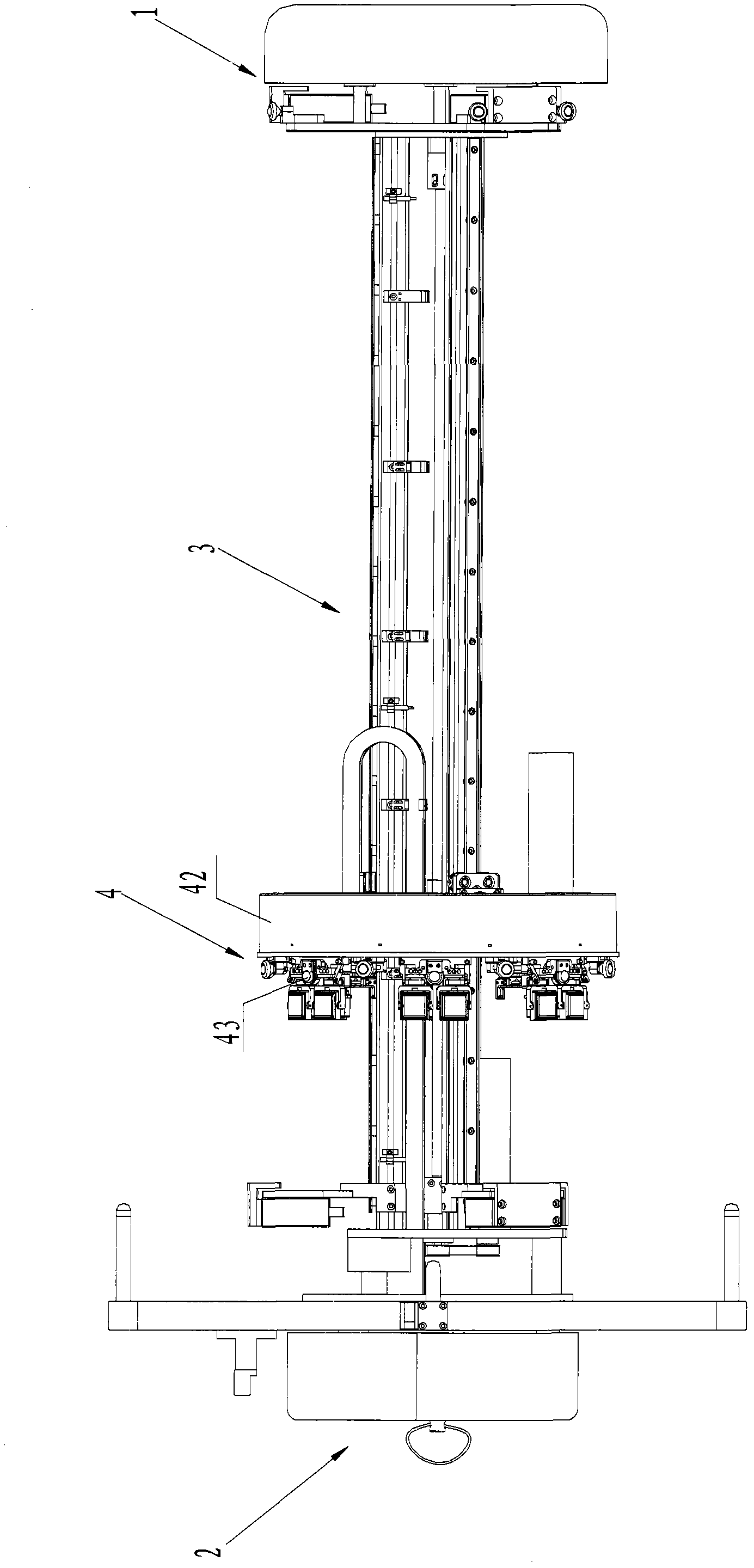
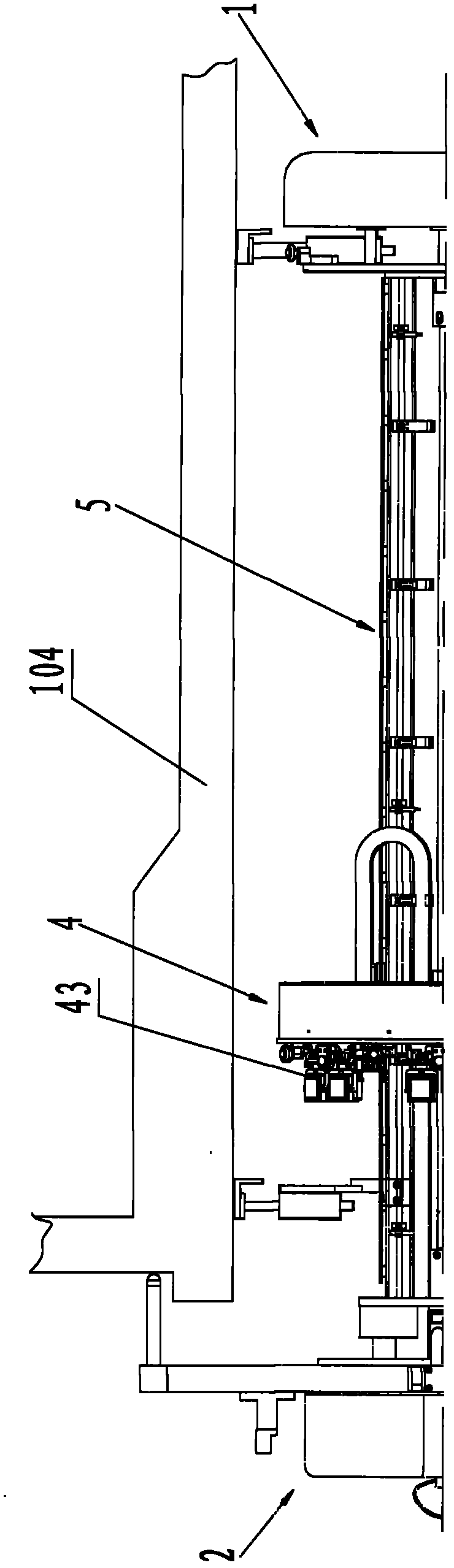
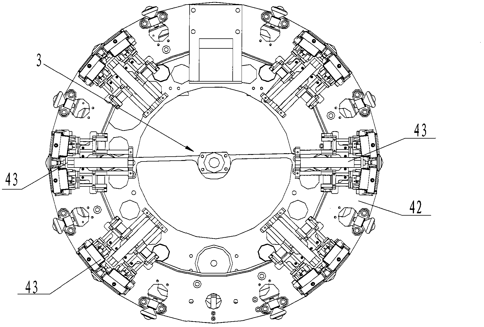
[0022] figure 1 and figure 2 The ultrasonic inspection equipment shown mainly consists of a front-end support module 1, a rear-end support module 2, a guide rail assembly 3 detachably connected between the front-end support module 1 and the rear-end support module 2, and a guide rail assembly 3 arranged on the relative The guide rail assembly 3 is composed of an ultrasonic probe scanning module 4 that performs axial linear movement and circumferential rotation. Among them, the front-end support module 1 mainly plays the role of guiding and radial positioning in the nozzle, the rear-end support module 2 is mainly used to realize the positioning of the equipment on the wall of the pressure vessel cylinder and along the axial direction of the nozzle, and the guide rail assembly 3 Mainly play the role o...


PUM


Abstract

The invention relates to a probe frame of a supersonic inspection device for a weld joint at a safe end of a nuclear reactor pressure vessel. Multiple groups of probe frames are distributed on a rotating disc along a circumferential direction, and the centers of all the probe frames are in the same plane. Each probe frame comprises a supersonic probe, a retainer connected with the supersonic probe, and two stages of linear motion mechanism connected with the retainer and used for driving the retainer to stretch or retract radially along the rotating disc; the first stage of linear motion mechanism is used for controlling the position of the probe frame relative to the rotating disc; the second stage of linear motion mechanism is used for controlling the position of the prove frame relative to a movable seat plate; under the restriction of the two stages of linear motion mechanism, the supersonic probe can effectively prevent scratching the inner wall of a pipe nozzle when in a retraction state and can ensure perfect coupling with the inner wall of the pipe nozzle for ensuring accurate and reliable scanning results when in a stretching sate.

Description

technical field [0001] The invention relates to the field of detection equipment for in-service / pre-service inspection of reactor pressure vessels of nuclear power plants, and in particular to ultrasonic inspection equipment and an ultrasonic probe frame for pressure vessel water outlets and water inlet nozzles. Background technique [0002] The nuclear reactor pressure vessel is one of the most important components of a nuclear power plant. It is used to fix, support and contain the core and all reactor internals. It is the only large-scale component that cannot be replaced during the entire life of the nuclear power plant. The quality of the nuclear reactor pressure vessel is the key to ensure the normal and safe operation of the nuclear power system. Figure 8 The shown nuclear reactor pressure vessel has a main body of a cylinder 101, the upper part of the cylinder 101 is connected with a hemispherical upper head (not shown in the figure) and a flange 102 through a bolt a...

Claims


Application Information

Patent Timeline
Patent Type & Authority Applications(China)
IPC IPC(8): G21C17/00
CPCY02E30/30
Inventor 陈怀东吴健荣李明刘金宏余哲
Owner CGNPC INSPECTION TECH
Why Eureka
Try Eureka