Optical member, backlight assembly and liquid crystal display device using the same

Inactive Publication Date: 2006-01-12
SAMSUNG DISPLAY CO LTD
View PDF10 Cites 59 Cited by
  • Summary
  • Abstract
  • Description
  • Claims
  • Application Information

AI Technical Summary

Benefits of technology

[0016] The present invention has been made to solve the above problems of prior arts, therefore, it is a first object of the present invention to provide an optical member capable of preventing scratches from being created on the optical member due to expansion of the optical member caused by heat and due to external vibration applied the optical member, without using an adhesive member.
[0017] A second object of the present invention is to provide a backlight assembly capable of displaying superior quality of images by preventing an optical member from being scratched due to expansion of the optical member caused by heat and due to external vibration applied the optical member, without using an adhesive member.
[0018] A third object of the present invention is to provide a liquid crystal display device capable of displaying superior quality of images by preventing an optical member from being scratched due to expansion of the optical member caused by heat and due to external vibration applied the optical member, without using an adhesive member.
[0021] To achieve the third object of the present invention, there is provided a liquid crystal display device comprising: a receiving container including i) a bottom face, ii) sidewalls protruded from edges of the bottom face to provide a receiving space, iii) a recess respectively formed on an upper portion of two opposite sidewalls of the receiving container, and iv) a fixing boss formed on a bottom surface of the recess and projected in parallel to the sidewalls; an optical module including a lamp and a first optical member, the lamp received in the receiving container to generate a first light, and the first optical member varying an optical characteristic of the first light to exit a second light; a second optical member including i) an optical body for varying the optical characteristic of the second light incident into the optical body to exit a third light, and ii) a first fixing part protruded from at least one side face of the optical body, the first fixing part including a fixing hole and a first vibration attenuating means, the fixing hole being elongated in a main expansion direction of the optical body to receive the fixing boss, and the vibration attenuating means being formed on an inner surface of the fixing hole to attenuate an external vibration applied to the optical body; a liquid crystal display panel assembly, disposed on the second optical member to be received in the receiving container, for changing the third light into a fourth light having image information; and a chassis, coupled to the receiving container on which the liquid crystal display panel assembly is received, for preventing the liquid crystal display panel assembly from being separated from the receiving container.
[0022] According to the present invention, the liquid crystal display device can display superior quality of images by absorbing external vibration applied thereto and simultaneously by allowing expansion of an optical member caused by heat generated from a lamp without deteriorating display quality.

Problems solved by technology

However, since the optical part is manufactured to have a thin sheet shape by using synthetic resin, the optical part easily expands by heat.
When the optical part expands in a state that the optical sheet is securely fixed by the double-faced adhesive tape, wrinkles are created on the optical part, so that display quality is deteriorated.
In other words, the wrinkles created on the optical part cause stains to be shown when images are displayed.
However, when the optical part is movably fixed, the optical part makes a friction with respect to the liquid crystal control part that is adjacent to the optical part due to external vibration applied to the optical part.
When friction occurs between the optical part and the liquid crystal control part, scratches are created on the liquid crystal control part or the optical part, thereby deteriorating display quality.

Method used


Image

  • Optical member, backlight assembly and liquid crystal display device using the same
  • Optical member, backlight assembly and liquid crystal display device using the same
  • Optical member, backlight assembly and liquid crystal display device using the same

Examples


embodiment 1

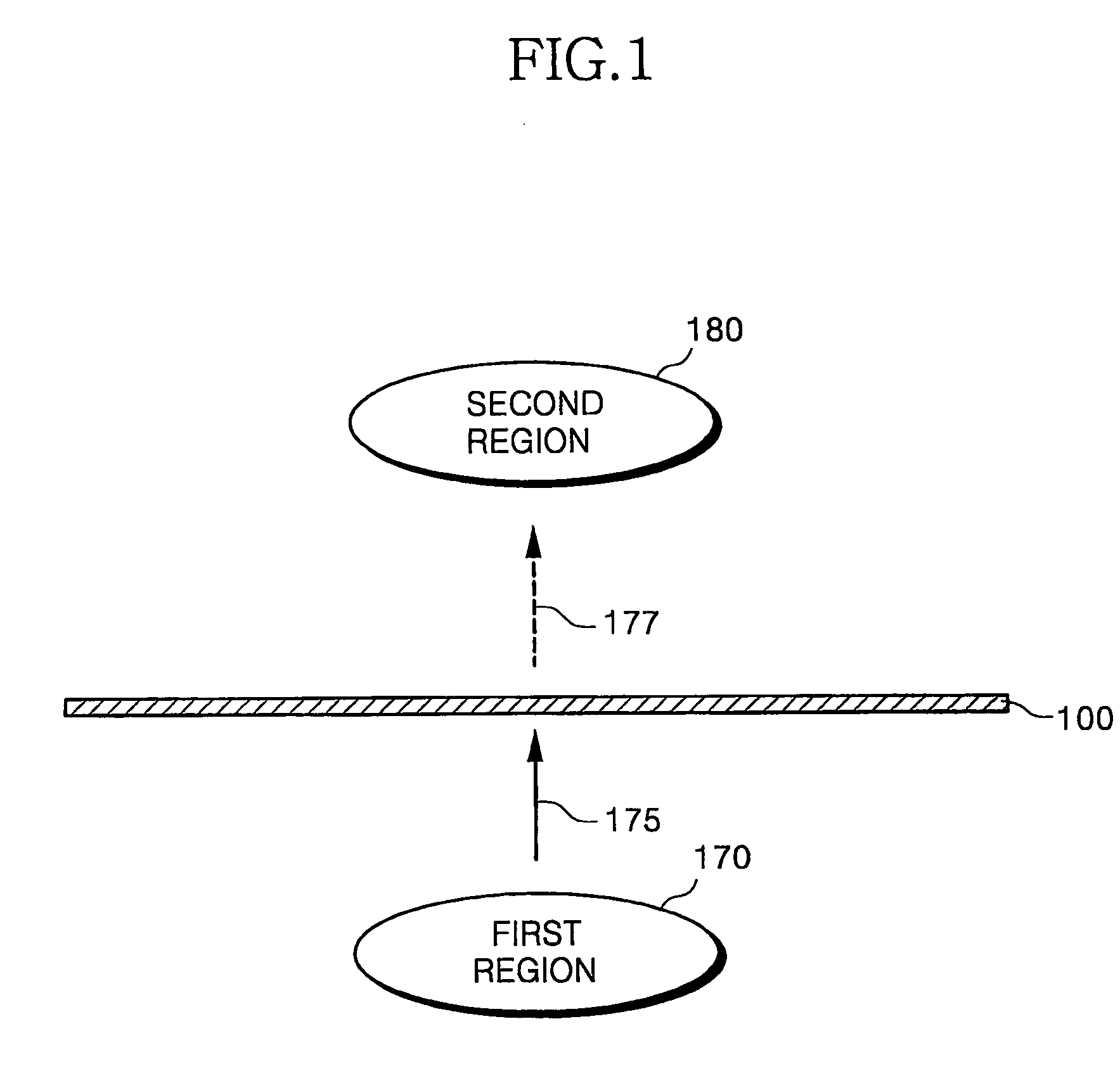
[0040]FIG. 1 is a side view showing an optical member 100 according to a first exemplary embodiment of the present invention.

[0041] Referring to FIG. 1, the optical member 100 varies optical characteristics of a first light 175 generated in a first region 170 to exit a second light 177 towards a second region 180.

[0042] The optical characteristics include, for example, brightness uniformity of light, orientation of light, and light usage efficiency.

[0043] When the optical member 100 satisfies the above optical characteristics, only one sheet of optical member 100 may be used. However, since it is difficult to satisfy the brightness uniformity of light, the orientation of light, and the light usage efficiency by means of only one sheet of optical member, three sheets of optical members 100 are typically employed.

[0044] The optical member 100 includes a diffusion sheet that exits a second light 177 by enhancing brightness uniformity of the first light 175.

[0045] The diffusion she...

embodiment 2

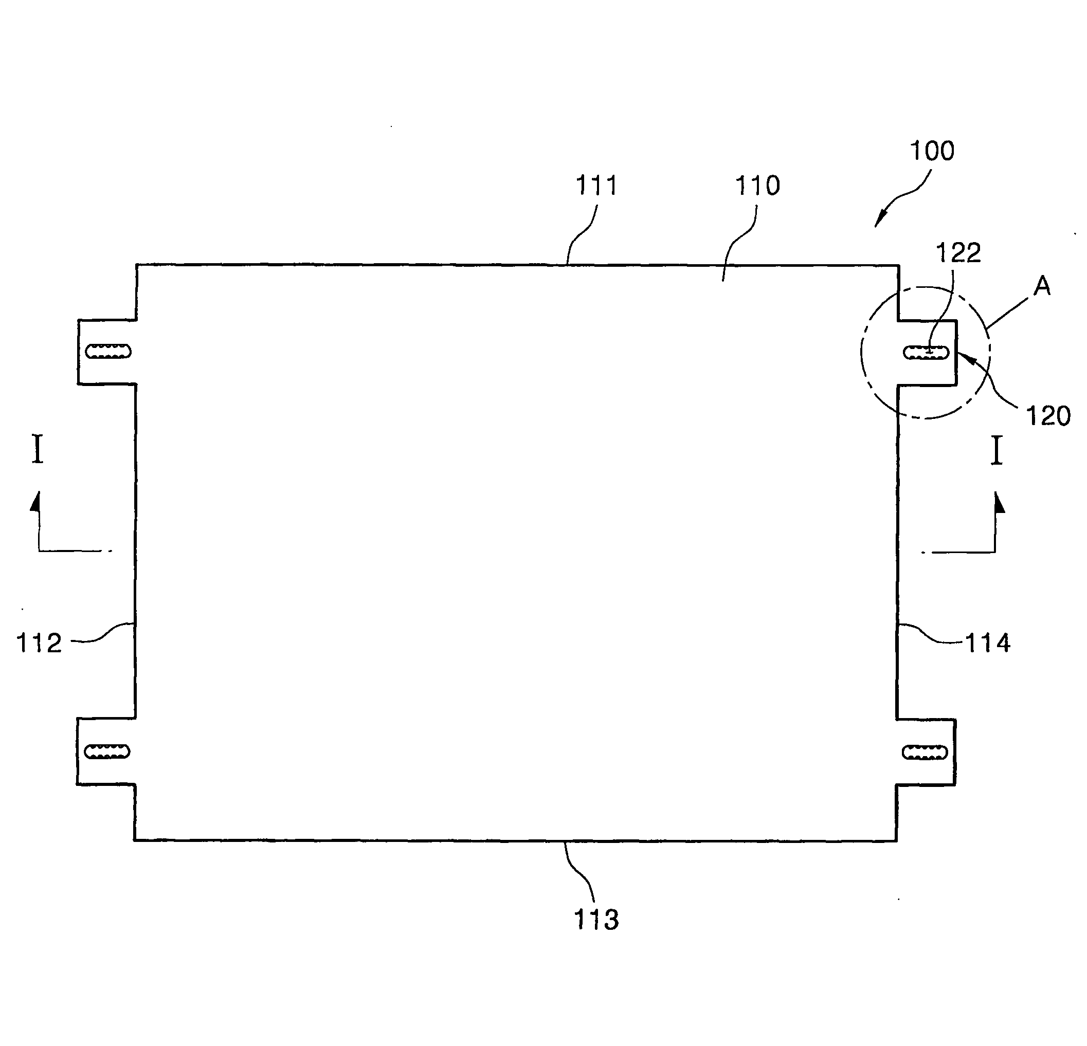
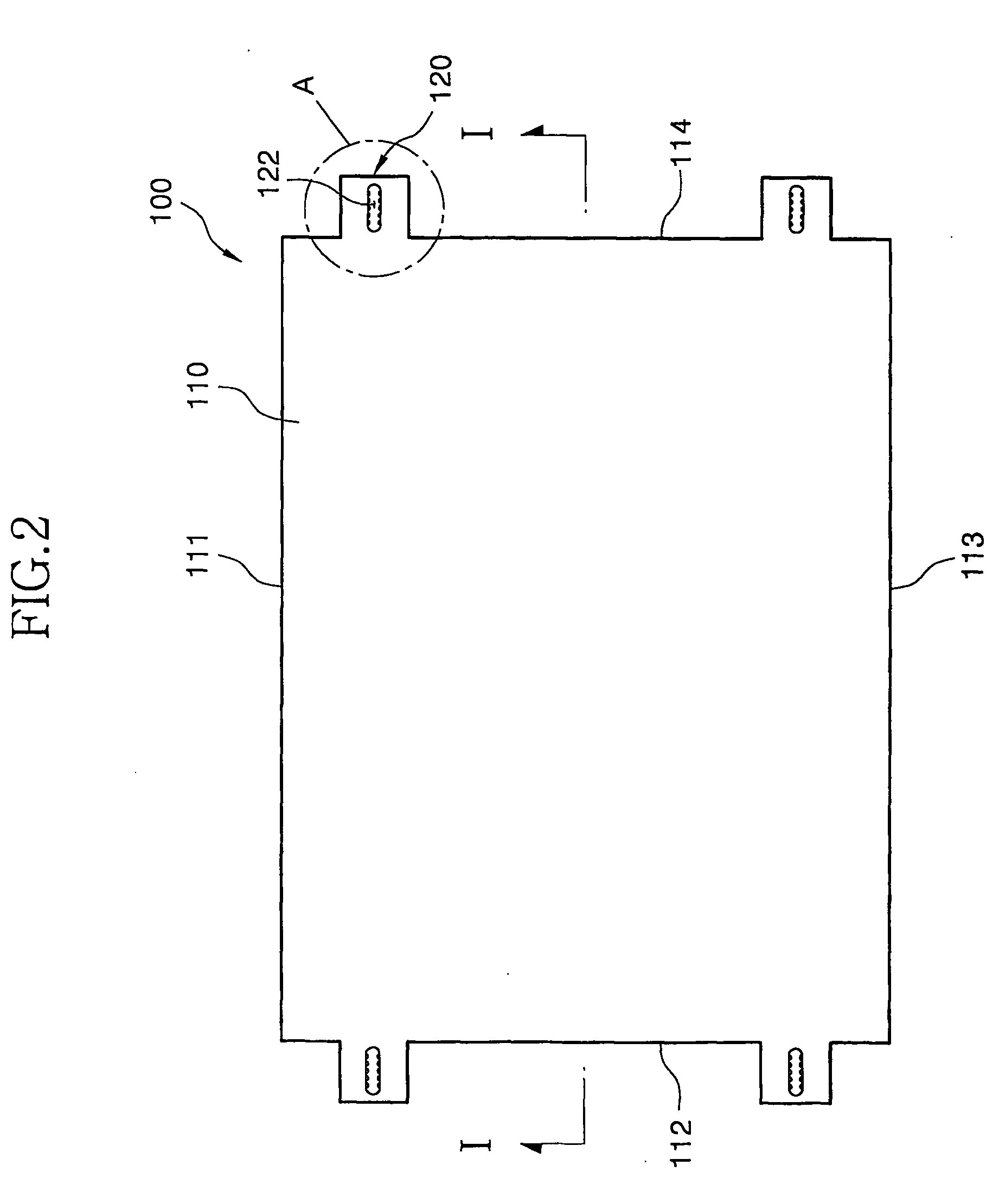
[0065]FIG. 4 is a plan view showing an optical member 100 according to a second exemplary embodiment of the present invention.

[0066] Referring to FIG. 4, the optical member 100 includes an optical body 110 and a first fixing part 130.

[0067] The optical body 110 has a rectangular parallelepiped sheet shape or a rectangular parallelepiped plate shape. Thus, the optical body 110 has four side faces 111, 112, 113 and 114.

[0068] At least one fixing part 130 is protruded from two opposite side faces 112 and 114, respectively.

[0069] Preferably, a pair of first fixing parts 120 are protruded from two opposite side faces 112 and 114, respectively. The fixing parts 120 formed on a side face of the optical body 110 are spaced from each other. The fixing parts 120 are protruded in parallel to an upper (or lower) surface of the optical body 130.

[0070]FIG. 5 is an enlarged view of “B” shown in FIG. 4.

[0071] Referring to FIG. 5, the first fixing part 130 has a fixing hole 132 and a vibration...

embodiment 3

[0075]FIG. 7 is a plan view showing an optical member according to a third exemplary embodiment of the present invention.

[0076] Referring to FIG. 7, the optical member 100 includes an optical body 110, a first fixing part 140 and a second fixing part 150.

[0077] The optical body 110 has a rectangular parallelepiped sheet shape or a rectangular parallelepiped plate shape. Thus, the optical body 110 has four side faces 111, 112, 113 and 114.

[0078] The first fixing part 140 is protruded from one side face 114. Preferably, at least one first fixing part 140 or a pair of first fixing parts 140, which are spaced by a predetermined distance from each other, are protruded from the side face 114, respectively.

[0079] The first fixing part 140 has a fixing hole 142 and vibration attenuating protrusions 144 identical to the fixing hole 132 and the vibration attenuating protrusions 134 described in the second exemplary embodiment. Thus, the shapes of the fixing hole 142 and the vibration atte...


PUM


Abstract

Disclosed are an optical member (100), a backlight assembly (500) and a liquid crystal display device (800) using the optical member. The optical member (100) includes an optical body (110) and a first fixing part (120). The optical body varies optical characteristic of first light incident into thereto to exit a second light. The first fixing part (120) is protruded from at least one side face of the optical body (110), and including a fixing hole (122) and a vibration attenuating means (124). The fixing hole (122) is elongated in a main expansion direction of the optical body (110), and the vibration attenuating means (124) is formed on an inner of the fixing hole to attenuate external vibration applied to the optical body (110). The fixing hole (122) allows movement of the optical member (100) in accordance with expansion of the optical member (100) caused by heat, thereby preventing wrinkles from being created on the optical body. The vibration attenuating member (124) prevents the optical body from being scratched.

Description

TECHNICAL FIELD [0001] The disclosure relates to an optical member, a backlight assembly and a liquid crystal display (LCD) device using the same, and more particularly to an optical member, a backlight assembly and a liquid crystal display device using the same, the optical member capable of preventing scratches from being created on the optical member due to external vibration without using an adhesive member, and allowing an movement of the optical member in accordance with expansion and contraction of the optical member caused by heat. BACKGROUND ART [0002] A liquid crystal display device is an appliance for displaying images by using liquid crystal. [0003] In order to display images, a conventional liquid crystal display device includes a light supplying part for generating light required for displaying images, an optical part for making brightness distribution of the light to be uniform, and a liquid crystal control part for controlling the liquid crystal. [0004] For example, ...

Claims


Application Information

Patent Timeline
IPC IPC(8): G02F1/1333G02F1/13G02F1/13357
CPCG02F1/133308G02F2201/54G02F2201/503G02F2001/133322G02F1/133322G02F1/1335
Inventor CHO, CHUN-HYUN
Owner SAMSUNG DISPLAY CO LTD
Why Eureka
Try Eureka