Electrical connector configured by wafer having coupling lead-frame and method for making the same

a technology of electrical connectors and lead frames, which is applied in the direction of coupling contact members, coupling device connections, electric discharge lamps, etc., can solve the problems of insufficient reliability of electrical connection between the connection portion and the specific terminal, high probability that the connector can be used for a long time, and large electrical coupling between adjacent terminals. to achieve the effect of reliable electrical coupling

Inactive Publication Date: 2010-10-28
HON HAI PRECISION IND CO LTD
View PDF17 Cites 16 Cited by
  • Summary
  • Abstract
  • Description
  • Claims
  • Application Information

AI Technical Summary

Benefits of technology

[0010]A primary object of the present invention is to provide an electrical connector capable of achieving reliable electrical coupling among the terminals.
[0012]The coupling lead-frame has a plurality of pin legs formed thereon for providing access to the terminals, to thereby establish a reliable electrical connection between the terminals and the coupling lead-frame. Therefore, the electrical compensation among the terminals is reliable.

Problems solved by technology

In such high speed applications, electrical coupling between adjacent terminals would create a great problem.
Unless the electrical coupling between the terminals could be controlled effectively within the connector to an accepted level, it is highly unlikely that the connector can be used for long time.
The electrical connection between the connection portion and the specific terminal is not reliable enough, by disposing the connection portion below the specific terminal.
Therefore, the electrical coupling between the selected terminal and the specific terminal is simultaneously unreliable.
It is easy to distort the connecting portions of the contacts and thus it would result in unreliable electrical compensation between the contacts and the circuit traces.

Method used


Image

  • Electrical connector configured by wafer having coupling lead-frame and method for making the same
  • Electrical connector configured by wafer having coupling lead-frame and method for making the same
  • Electrical connector configured by wafer having coupling lead-frame and method for making the same

Examples


Embodiment Construction

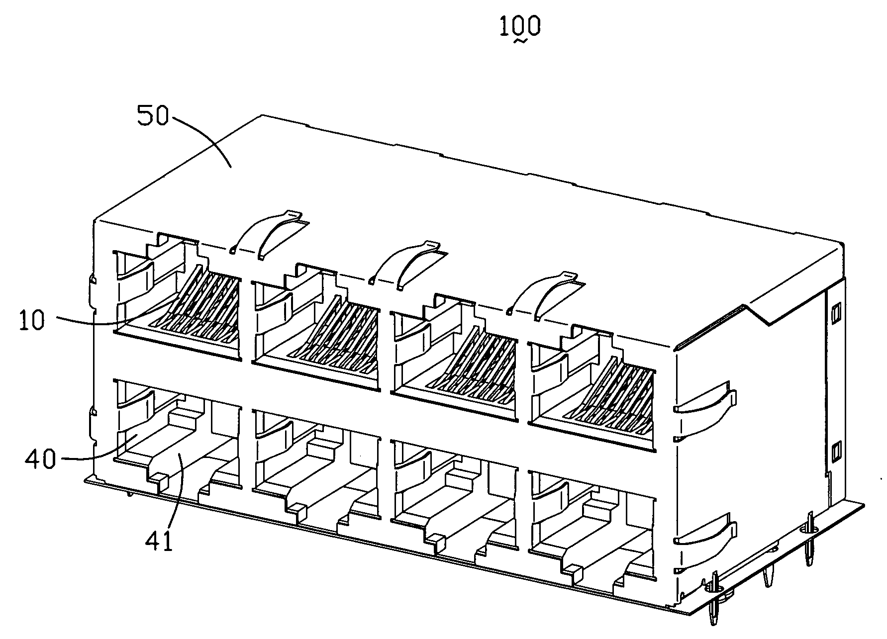
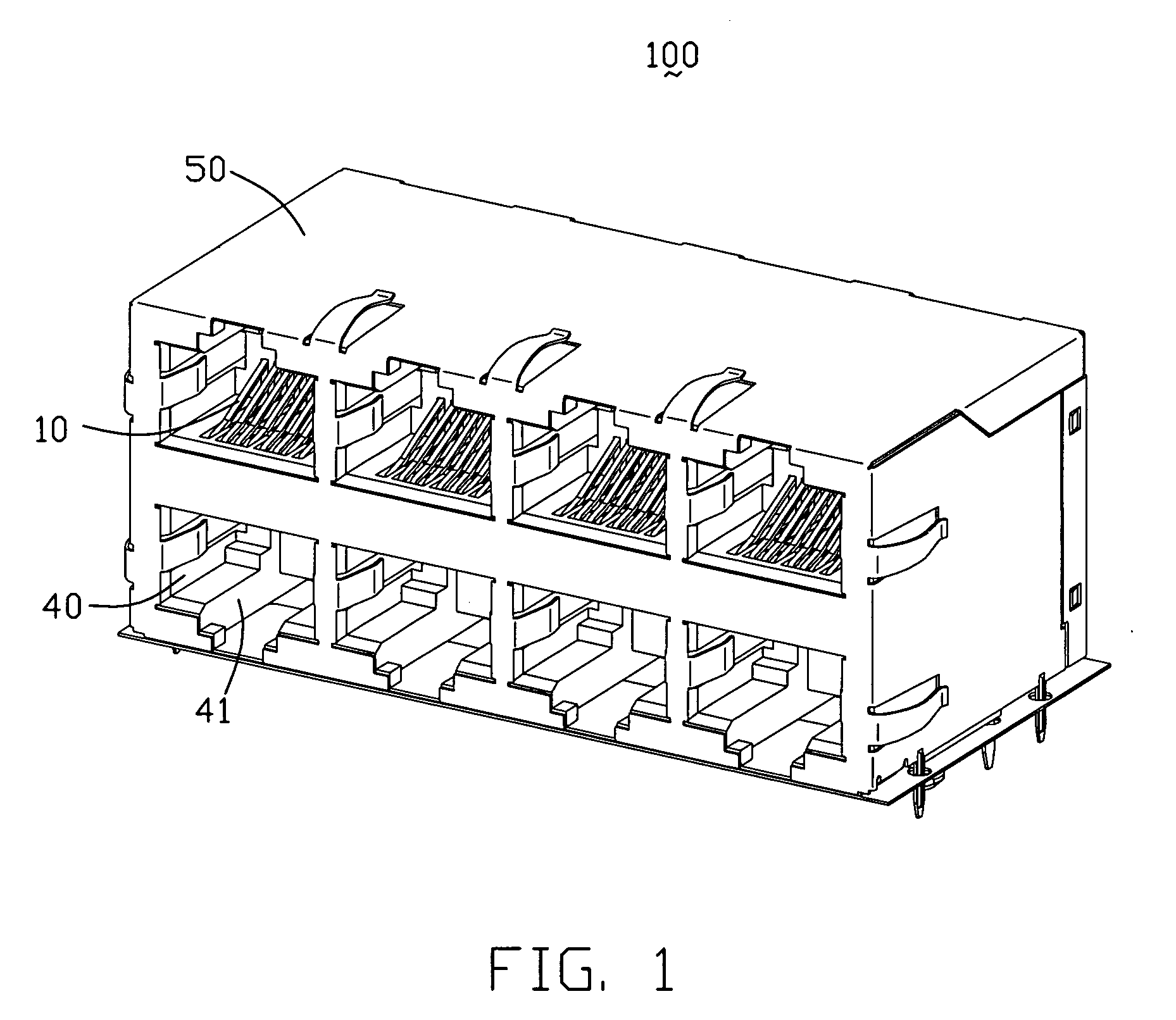
[0026]Reference will now be made to the drawing figures to describe the present invention in detail. Referring to FIG. 1, an electrical connector 100 in accordance with the preferred embodiment of the present invention comprises an insulative housing 40 defining a plurality of cavities 41, a plurality of terminal modules 10 received in the cavities 41, and a shielding shell 50 attached to the insulative housing 40. In another embodiment, the terminal module 10 could be applied in other structure.

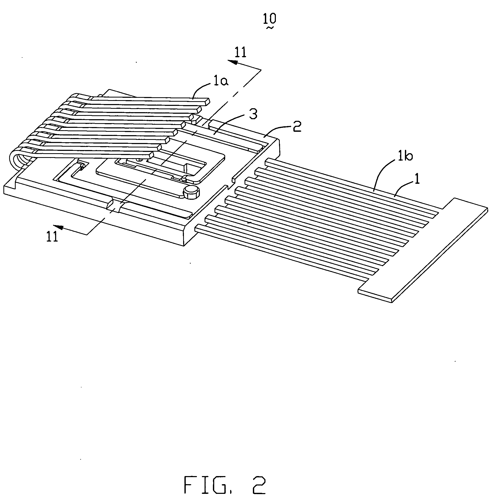
[0027]Referring to FIG. 2, each terminal module 10 comprises a coupling lead-frame 3, a dielectric wafer 2 and a plurality of terminals 1. The dielectric wafer 2 in accordance with the present invention is configured by insert-molding the terminals 1, typically eight, altogether, i.e., first through eighth terminals 11-18. According to the certain application, electrical couplings are respective produced between first and the third terminals 11 and 13, the third and fifth terminals 13 and 15...


PUM


Abstract

An electrical connector (100) includes an insulative housing (40) and a terminal module (10) retained in the insulative housing and configured with a selected terminal (11), a determined terminal (12) and a specific terminal (13) molded within a dielectric wafer (2). A coupling lead-frame (3) is disposed onto a surface of the dielectric wafer and has its main portion (3a) parallel and aligned with the specific terminal. The coupling lead-frame includes one pin leg (311) crossing over the determined terminal and having a physical and electrical engagement with the selected terminal so as to establish an electrical coupling between the selected terminal and the specific terminal.

Description

BACKGROUND OF THE INVENTION[0001]1. Field of the Invention[0002]The present invention relates to an RJ modular jack, and particularly, to an RJ modular jack configured by a wafer on which coupling traces are provided so as to create electrical coupling between selected terminals disposed within the wafer.[0003]2. Description of Related Art[0004]To comply with a high speed trend of data transmission, electrical devices are required to have better performance. Performance requirements have significantly increased to a level identified by industry standards as Category 5. The Telecommunications Industry Association (TIA) in corporation with the Electronic Industries Association (EIA) has developed a proposed standard for Category 5 components. In such high speed applications, electrical coupling between adjacent terminals would create a great problem. Unless the electrical coupling between the terminals could be controlled effectively within the connector to an accepted level, it is hi...

Claims


Application Information

Patent Timeline
Patent Type & Authority Applications(United States)
IPC IPC(8): H01R24/00H01R33/00
CPCH01R13/6658H01R13/6467H01R24/64
Inventor WALKER, KEVIN E.LITTLE, TERRANCE
Owner HON HAI PRECISION IND CO LTD
Why Eureka
Try Eureka