Ankle Rehabilitation Device

a rehabilitation device and ankle technology, applied in the field of ankle rehabilitation devices, can solve the problems of limited use, difficult use of devices capable of targeting specific muscles or tendons, and simple devices are generally not adequate for the task of rehabilitating ankles, and achieve the effect of variable loading on targeted muscles and tendons and variable resistan

Inactive Publication Date: 2010-10-28
TERRIO TIMOTHY
View PDF4 Cites 13 Cited by
  • Summary
  • Abstract
  • Description
  • Claims
  • Application Information

AI Technical Summary

Benefits of technology

[0005]The disclosed device may be utilized for targeting specific muscles and tendons of the ankle by proving a load which may be pivoted about the ankle at a large range of angles. The disclosed device provides variable loading on targeted muscles and tendons, by utilizing a variable length moment arm to which the load is attached. Thus, the device provides a variable resistance on the ankle muscles and tendons when the ankle is moved, and may target different muscles and tendons by changing the angle of the resistance. The device comprises a foot retention member and a weight support member, with the weight support member comprising a removable weight. The weight support member is be rotatable relative to the foot retention member. The foot retention member comprises foot attachment means such as straps or bindings to retain the user's foot against the foot retention member.

Problems solved by technology

Although these devices serve the purpose of enabling movement of the person's ankle against a resistance load to effect a strengthening or conditioning of the ankle, the simpler form of these devices are generally not adequate to the task of rehabilitating ankles where specific muscles or tendons are targeted for strengthening or conditioning.
The devices which are capable of targeting specific muscles or tendons are generally difficult to use, are cumbersome, and are limited to use in controlled environments under the supervision of a therapist.

Method used


Image

  • Ankle Rehabilitation Device
  • Ankle Rehabilitation Device
  • Ankle Rehabilitation Device

Examples


Embodiment Construction

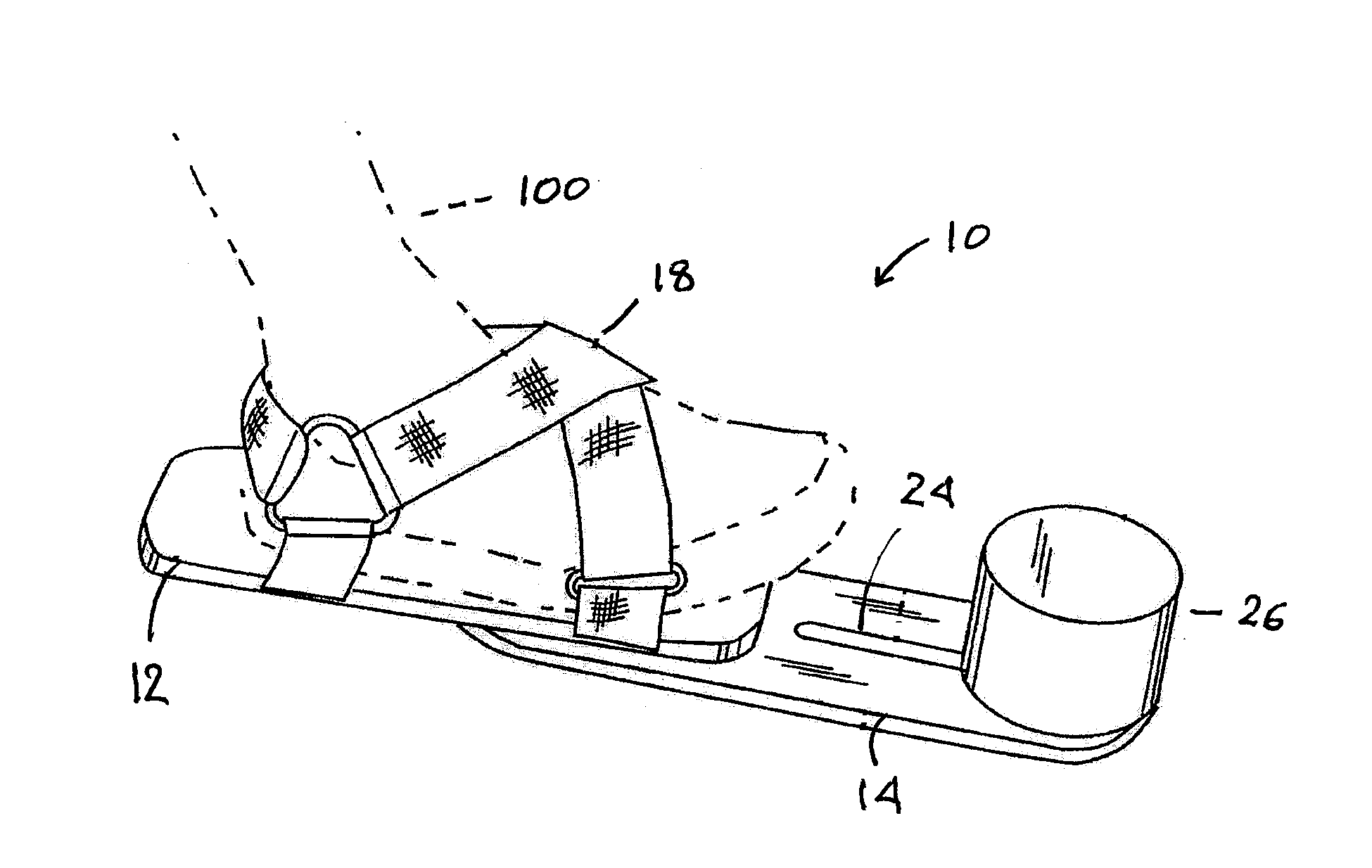
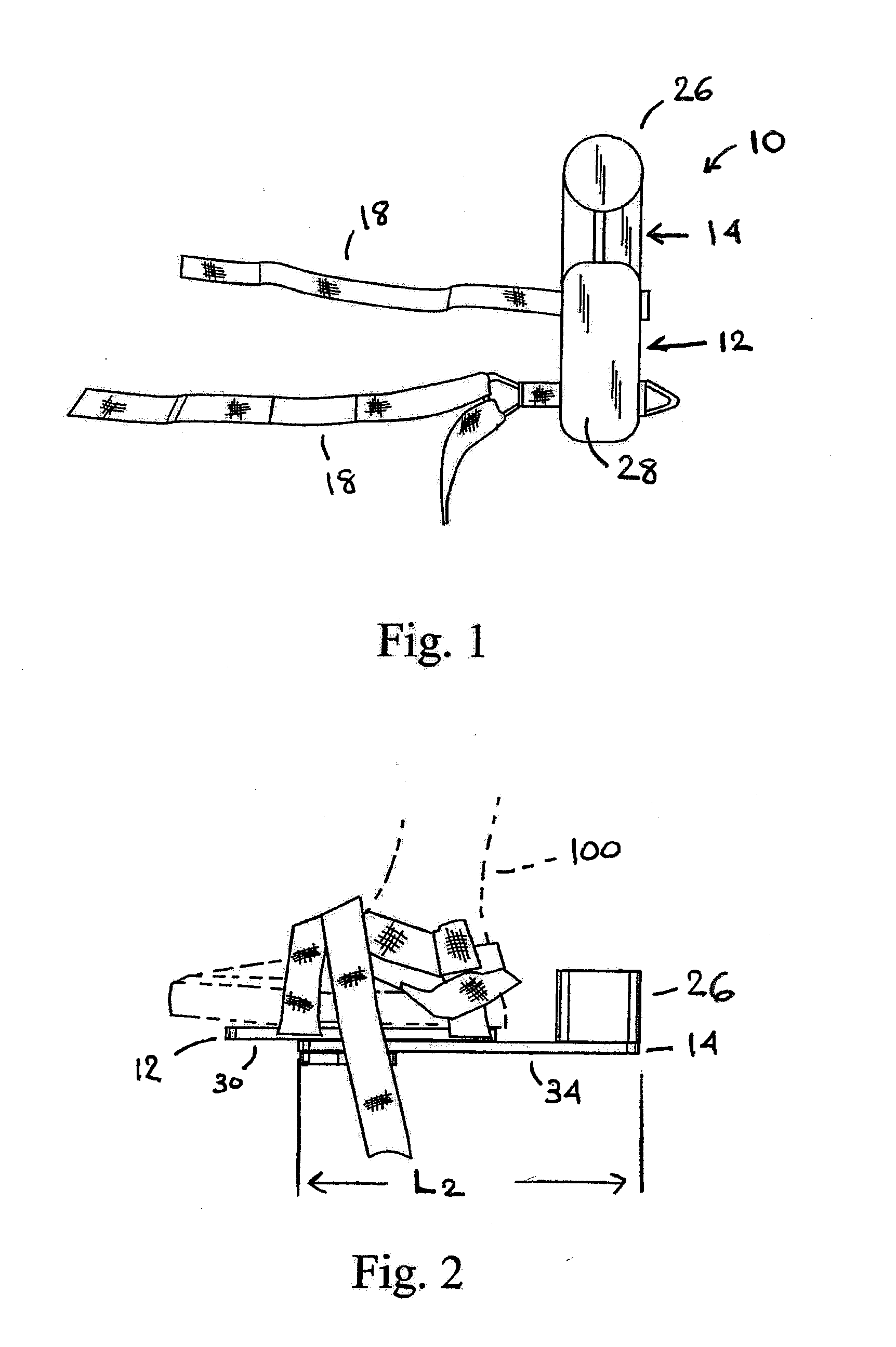
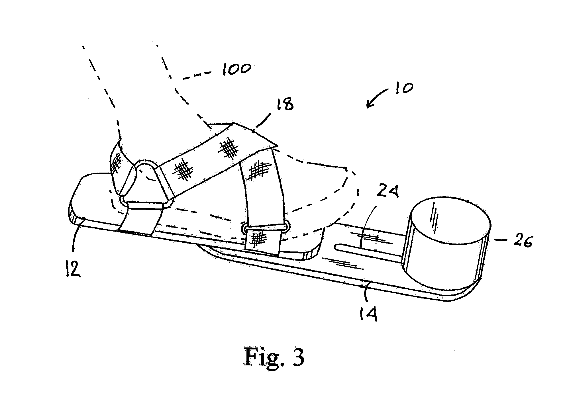
[0014]Referring now to the Figures, FIGS. 1 through 7 show various views of embodiments of the disclosed ankle rehabilitation device. Embodiments of the ankle rehabilitation device 10 comprise a foot retention member 12, a weight support member 14, and a weight 26. The foot retention member comprises a first top surface 28, a first bottom surface 30, a first length L1 which defines a first axis A1, and a first width W1.

[0015]The foot retention member 12 further comprises foot attachment means such as straps 18, bindings, or an integral shoe, to retain the users foot 100 against the foot retention member 12.

[0016]Weight support member 14 comprises a second top surface 32, a second bottom surface 34, a second length L2 which defines a second axis A2, and a second width W2. The weight support member 14 is rotatably attached to the foot retention member 12 by a pivoting means such as a stud 20, bolt, bushing, or other attachment means which enables the weight support member 14 to be rot...


PUM


Abstract

An ankle therapy device provides variable loading on targeted muscles and tendons, by utilizing a variable length moment arm to which the load is attached, and having the ability to change the angle of the load with respect to the orientation of the user's foot. Thus, the device provides a variable resistance on the ankle muscles and tendons when the ankle is moved, and may target different muscles and tendons by changing the angle of the resistance. The device comprises a member to which the user's foot is attached, and a rotatably attached weight support member to which a weight is secured. The position of the weight may be shifted along the length of the weight support member, and the amount of weight may be changed.

Description

CROSS-REFERENCE TO RELATED APPLICATION[0001]U.S. Provisional Application No. 61 / 214,383 for this invention was filed on Apr. 22, 2009, for which application this inventor claims domestic priority.BACKGROUND[0002]The disclosed apparatus generally relates to devices used during physical rehabilitation and specifically to devices used in physical rehabilitation directed towards strengthening the leg muscles, calves, and the ankle.[0003]It is known to use various exercising devices for the purpose of rehabilitating or conditioning the muscles and tendons associated with the ankle joint. Typically, these devices involve a shoe-like apparatus designed to be attached to a person's foot and the shoe is then mounted to a load inducing machine or piece of equipment so that the person's ankle joint can be maneuvered in different ways against the resistance produced by the equipment.[0004]Although these devices serve the purpose of enabling movement of the person's ankle against a resistance lo...

Claims


Application Information

Patent Timeline
Patent Type & Authority Applications(United States)
IPC IPC(8): A61H1/02
CPCA61H1/0266A61H2201/165A63B23/08A63B21/143A63B21/065A63B21/4015
Inventor TERRIO, TIMOTHY
Owner TERRIO TIMOTHY
Why Eureka
Try Eureka