Captive fastener with unique engaging and locking mechanism

a technology of locking mechanism and captive fastener, which is applied in the field of captive fasteners, can solve the problems of significant time-consuming removal and questionable longevity of the fastener, and achieve the effect of ensuring variable-sized loads and reducing vibration

Inactive Publication Date: 2010-07-06
LOCKHEED MARTIN CORP
View PDF12 Cites 5 Cited by
  • Summary
  • Abstract
  • Description
  • Claims
  • Application Information

AI Technical Summary

Benefits of technology

[0007]It is therefore a principal object and advantage of the present invention to provide a fastener that engages and disengages with less than a full rotation to ease the difficulty associated with removal and securing the fastener, as well as increasing the speed with which fastener manipulation can be performed.
[0008]It is another object and advantage of the present invention to provide a fastener that minimizes affects of vibration.
[0009]It is a further object and advantage of the present invention to provide a fastener that can secure variable sized loads.
[0010]Other objects and advantages of the present invention will in part be obvious, and in part appear hereinafter.SUMMARY OF THE INVENTION
[0011]In accordance with the foregoing objects and advantages, the present invention provides a captive fastener generally comprising a receptacle, a bayonet assembly, and a locking assembly for locking the bayonet assembly to the receptacle. The receptacle extends along a longitudinal axis and includes a bore formed longitudinally therein that is defined by an interior surface and extends from its open end to a shoulder formed within the receptacle, a first raceway formed in the interior surface and extending in a predetermined pattern along at least a portion of the length of the interior surface, and a keyway formed in axial alignment and fluid communication with the bore and extending axially from the shoulder. The bayonet assembly comprises an elongated, hollow shaft adapted for axial engagement within the bore, and a first bayonet extending outwardly from the shaft and adapted for seated engagement within the first raceway. The locking assembly is mounted for axial movement within the hollow shaft and includes a key that moves between engaged (locked) and disengaged (unlocked) relation relative to the keyway.
[0012]In one aspect of the present invention the raceway extends in a spiral pattern longitudinally along the interior surface and revolves between about 120 and 180 degrees around the interior surface. Preferably, the raceway revolves about 120 degrees around the interior surface and extends essentially the full length thereof. This geometry produces a fastener that requires approximately one quarter turn to less than one half turn of a tool engaged with the receptacle to fasten or unfasten the fastener.

Problems solved by technology

Due to the number of fasteners and the strength associated with these fasteners, it takes significant time to remove them.
For instance, fasteners used on one radar transmitter cover exceed 12 minutes to remove and recommended industry fasteners are threaded and require up to 8 turns to seat; the longevity associated with these fasteners are questionable, as is reliability due to captive washer breaks.

Method used


Image

  • Captive fastener with unique engaging and locking mechanism
  • Captive fastener with unique engaging and locking mechanism
  • Captive fastener with unique engaging and locking mechanism

Examples


Embodiment Construction

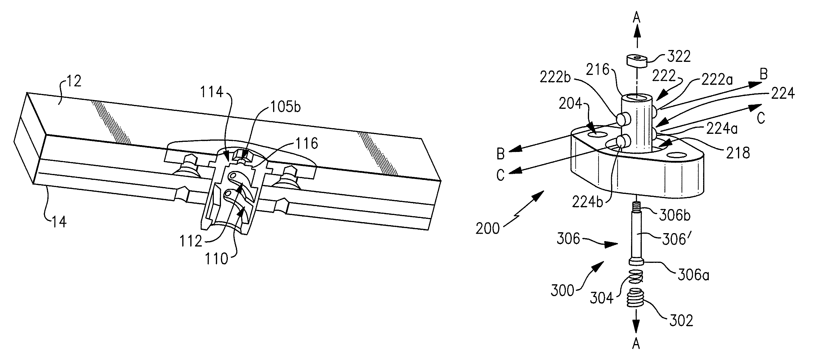
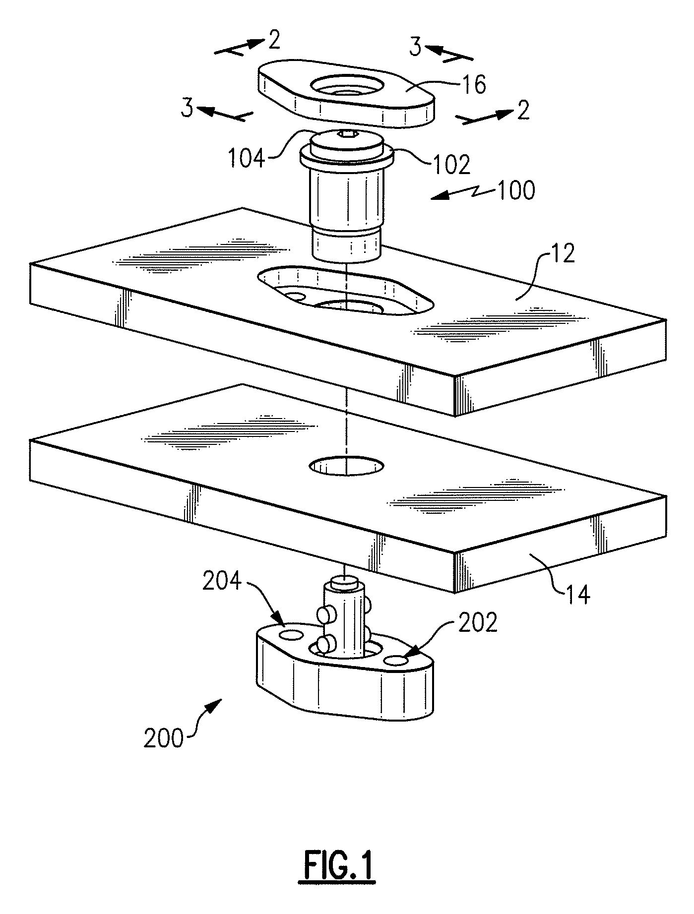
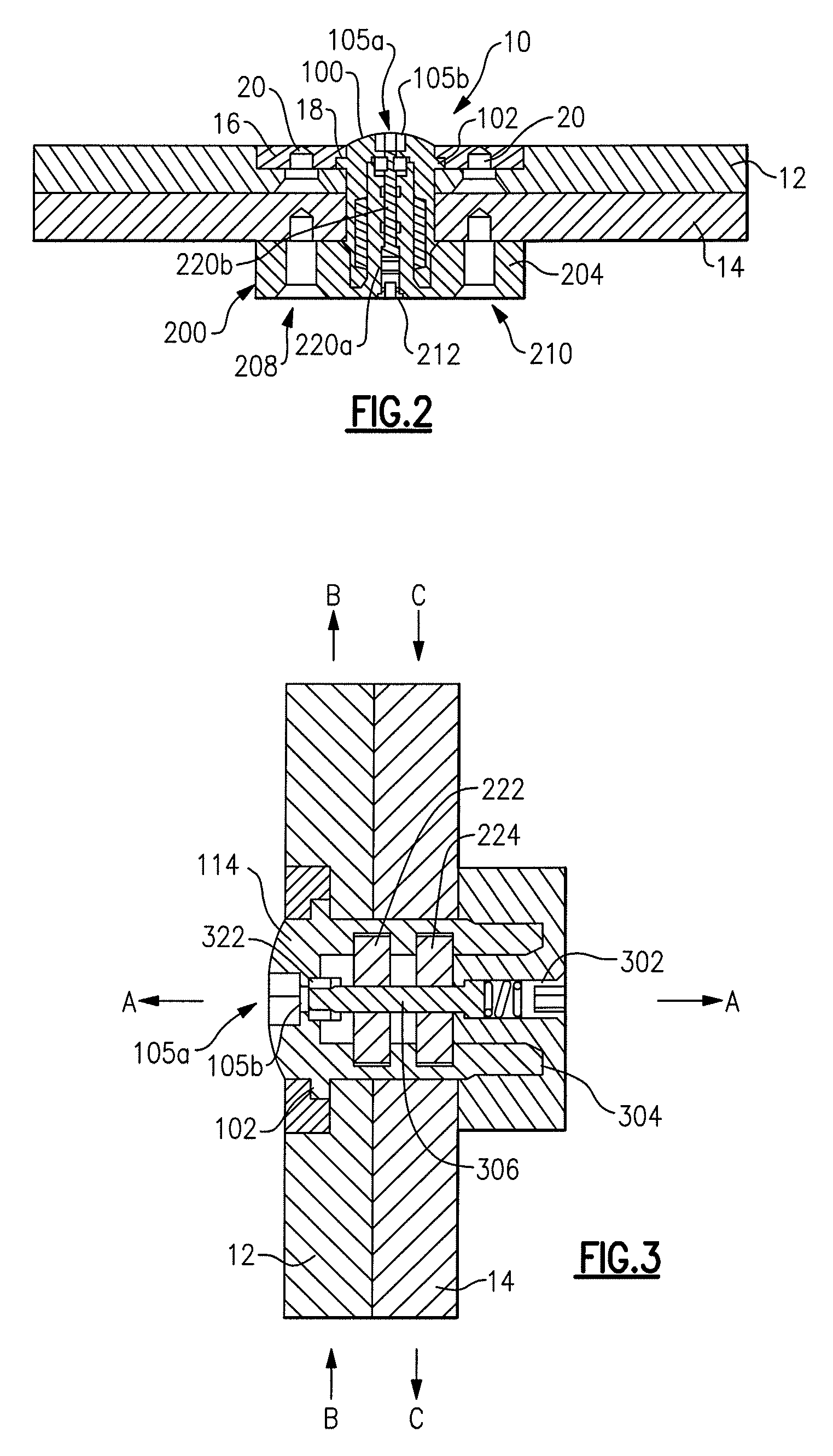
[0027]With reference to the drawings, in which like reference numerals refer to like parts throughout, there is seen in the Figures a captive fastener, designated generally by reference numeral 10, a plurality of which may be used to fasten a removable panel 12 to a fixed substructure 14. Captive fastener 10 generally comprises a receptacle 100, a bayonet assembly 200, and a locking assembly 300 that lockingly engages and permits disengagement of bayonet assembly 200 relative to receptacle 100. More specifically, receptacle 100 is secured to removable panel 12 by a head 16 that including a countersunk opening 18 that receives and clamps a circumferential flange 102 formed on the head 104 of receptacle 100 between itself and panel 12. A pair of rivets 20 fasten head 16 to panel 12, thereby creating a unitary assembly of panel 12 and receptacle 100.

[0028]Bayonet assembly 200 is secured to fixed substructure 14 by a pair of bolts or other fasteners that extend through a pair of opening...


PUM

PropertyMeasurementUnit
lengthaaaaaaaaaa
movementaaaaaaaaaa
dimensionaaaaaaaaaa

Abstract

A captive fastener generally comprising a receptacle, a bayonet assembly, and a locking assembly for locking the bayonet assembly to the receptacle. The receptacle extends along a longitudinal axis and includes a pair of parallel extending spiral raceways formed in the inner surface of a central opening that extends therethrough, and a keyway formed adjacent its terminus. The bayonet assembly includes a pair of bayonets that are adapted to ride in the raceways and a key positioned at the end of a plunger and is adapted to engage the keyway thereby locking the bayonet assembly in the receptacle. The locking assembly includes the plunger that when manipulated by a tool either engages or disengages the key from the keyway.

Description

BACKGROUND OF THE INVENTION[0001]1. Field of Invention[0002]The present invention relates generally to fasteners and more particularly to captive fasteners used to secure components in racks in high vibration and other hostile environments.[0003]2. Description of Prior Art[0004]Racks are used to house electronic components and devices, such as RADAR transmitters, computers, and the like. Oftentimes, these racks are included on moving articles, such as ships, aircraft, and other articles that induce vibrations to the racks. To maintain a clean environment for the rack mounted components as well as secure their positions within the rack, captive fasteners are used to attach panels and other items to the rack to improve structural and environmental integrity. The term “captive” refers to the fixed engagement of one part of the fastener in a panel / cover and the fixed engagement of the second part of the fastener in the rack / housing to which the panel / cover is to be attached.[0005]When t...

Claims


Application Information

Patent Timeline
Patent Type & Authority Patents(United States)
IPC IPC(8): F16B21/00
CPCF16B5/10H05K7/1407Y10T29/53657
Inventor BULOW, JEFFREY A.GAGNON, RONALD D.AMIDON, JERAMY K
Owner LOCKHEED MARTIN CORP
Why Eureka
Try Eureka