Adaptive loading of a fuel cell

a fuel cell and adaptive technology, applied in the field of fuel cell systems, can solve the problems of reducing the performance reducing the efficiency of the fuel cell, and corroding the cathode electrode, so as to facilitate the adaptive and variable electrical load applied, and minimize the degradation of the fuel cell system

Active Publication Date: 2014-06-10
GM GLOBAL TECH OPERATIONS LLC
View PDF16 Cites 0 Cited by
  • Summary
  • Abstract
  • Description
  • Claims
  • Application Information

AI Technical Summary

Benefits of technology

[0012]Concordant and consistent with the present invention, a fuel cell system and a method for facilitating an adaptive and variable electrical load applied to a fuel cell system during startup, while also minimizing degradation of the fuel cell system due to a non-uniform hydrogen distribution across an anode, has surprisingly been discovered.

Problems solved by technology

High RHE potential on the cathode electrode can rapidly corrode the cathode electrode, and is known to degrade fuel cell performance.
Importantly, during startup of a fuel cell with high electrical load demand, the non-uniform distribution of hydrogen on the anodes of the fuel cell stack can lead to a phenomenon known as “cell reversal.” Cell reversal occurs when a load is applied to the fuel cell stack and when at least one fuel cell in the fuel cell stack lacks sufficient hydrogen to support a current generated by the other fuel cells in the fuel cell stack supplied with adequate hydrogen.
The other cells in the stack cause a locally higher electric potential to that portion of the anode lacking sufficient hydrogen, leading to an oxidation of the carbon support in this region of the anode of the reversed cell that may result in a rapid voltage degradation of the fuel cell, significantly reducing the useful life of the fuel cell stack.
In particular, a corrosion of the carbon substrate of the anode electrode of the starved cell, wherein CO and CO2 are formed, occurs.
However, fixed resistance loads may not match the minimum charge draw.
In addition, a low-impedance circuit typically requires costly high current capacity components or else requires some mechanism to slow the hydrogen-air front.
However, the fixed resistive load requires the addition of electrical components to engage the fixed resistive load.
Further, the resistive load itself adds to the cost and complexity of the system, creating reliability concerns.
A fixed resistive load does not allow the electric load to be adjusted based on the needs of the stack or the fuel cell system.
However, such a method requires a high precision control of both the delivery of reactants to the anode electrode and application of the dead short.

Method used


Image

  • Adaptive loading of a fuel cell
  • Adaptive loading of a fuel cell
  • Adaptive loading of a fuel cell

Examples


Embodiment Construction

[0021]The following detailed description and appended drawings describe and illustrate various embodiments of the invention. The description and drawings serve to enable one skilled in the art to make and use the invention, and are not intended to limit the scope of the invention in any manner. In respect of the methods disclosed, the steps presented are exemplary in nature, and thus, the order of the steps is not necessary or critical.

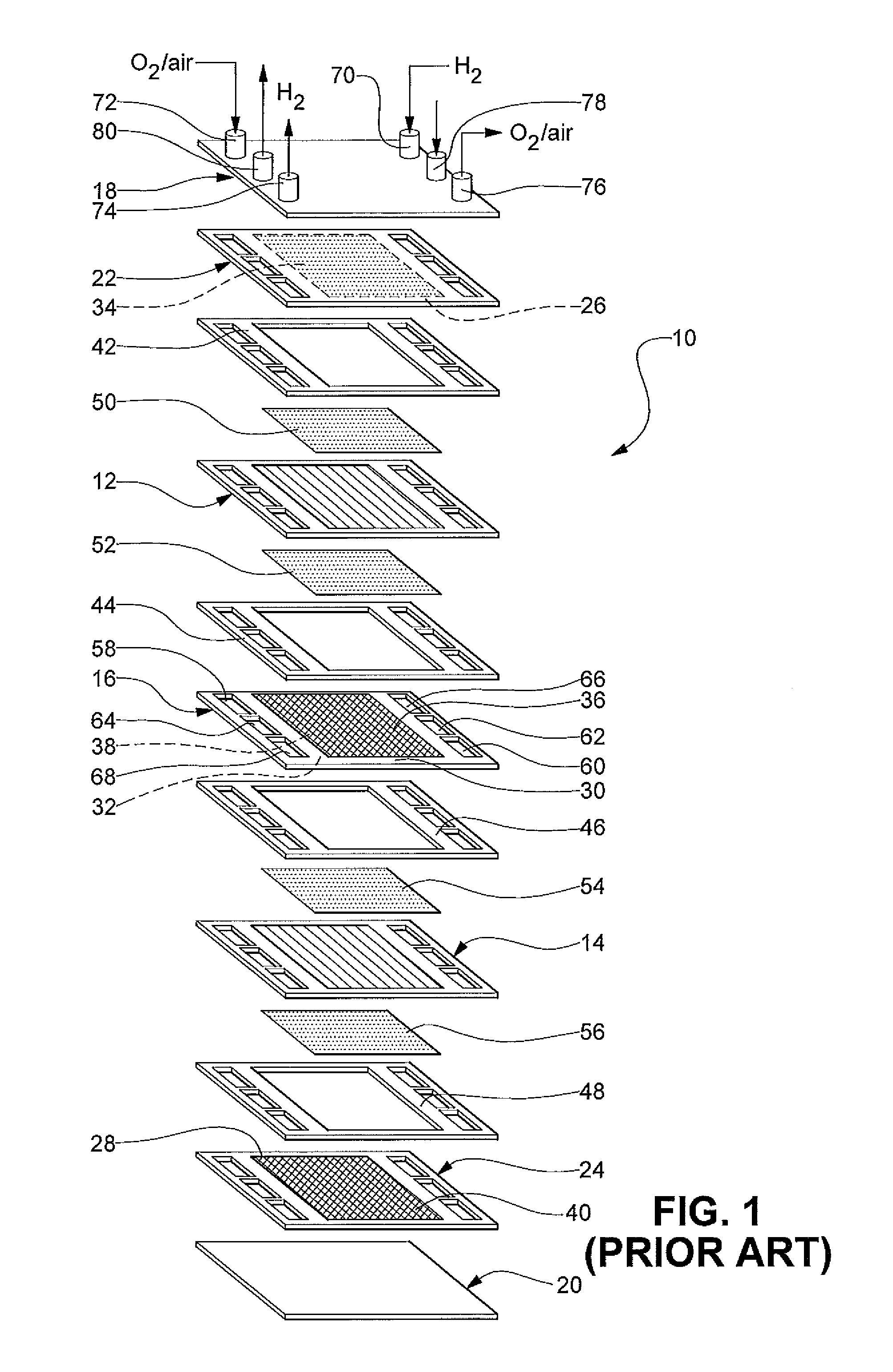
[0022]FIG. 1 illustrates a PEM fuel cell stack 10 according to the prior art. For simplicity, only a two-cell stack (i.e. one bipolar plate) is illustrated and described in FIG. 1, it being understood that a typical fuel cell stack will have many more such cells and bipolar plates. The fuel cell stack 10 includes a pair of membrane electrode assemblies (MEAs) 12, 14 separated by an electrically conductive bipolar plate 16. The MEAs 12, 14 and the bipolar plate 16 are stacked between a pair of clamping plates 18, 20 and a pair of unipolar end plates 22...


PUM

PropertyMeasurementUnit
electrical currentaaaaaaaaaa
voltageaaaaaaaaaa
currentaaaaaaaaaa

Abstract

A fuel cell system is disclosed with a fuel cell stack having a plurality of fuel cells, the fuel cell stack including an external electrical circuit adapted to control current from the fuel cell stack, a sensor for measuring at least one of an environmental condition affecting the fuel cell stack and a characteristic of the fuel cell stack, wherein the sensor generates a sensor signal representing a measurement of the sensor, and a processor for receiving the sensor signal, analyzing the sensor signal, and controlling an adaptive load applied to the external electrical circuit based upon the analysis of the sensor signal.

Description

FIELD OF THE INVENTION[0001]The invention relates to fuel cell systems. More particularly, the invention is directed to a fuel cell system and a method for mitigating periods of high electrode potential to protect the fuel cell from damaging currents.BACKGROUND OF THE INVENTION[0002]A fuel cell has been proposed as a clean, efficient and environmentally responsible power source for electric vehicles and for various other applications. In particular, the proton exchange membrane (PEM) fuel cell has been identified as a potential alternative for a traditional internal-combustion engine used in modern vehicles.[0003]The PEM fuel cell includes three basic components: a cathode, an anode and an electrolyte membrane. The cathode and anode typically include a finely divided catalyst, such as platinum, supported on carbon particles and mixed with an ionomer. The electrolyte membrane is sandwiched between the cathode and the anode to form a membrane electrode assembly (MEA). The MEA is often...

Claims


Application Information

Patent Timeline
Patent Type & Authority Patents(United States)
IPC IPC(8): H01M8/04
CPCH01M8/0432H01M8/04388H01M8/04552H01M8/0438H01M8/0491H01M8/0494H01M8/04559Y02E60/50H01M8/04223H01M8/04589H01M8/04955H01M8/04037H01M8/04582H01M8/04447Y10T307/735H01M8/0267H01M8/242H01M8/04225H01M8/04228H01M8/04302H01M8/2483
Inventor ROBB, GARY M.GOEBEL, STEVEN G.HARRIS, DANIEL I.
Owner GM GLOBAL TECH OPERATIONS LLC
Why Eureka
Try Eureka