
Determining the position of an object

Active Publication Date: 2010-10-28
ABB (SCHWEIZ) AG
View PDF15 Cites 38 Cited by
  • Summary
  • Abstract
  • Description
  • Claims
  • Application Information

AI Technical Summary

Benefits of technology

[0044]This can improve the image quality of the relevant image, thus resulting in better determination of the position of an object by the evaluation system.

Problems solved by technology

However, this represents a practical situation which may occur rarely.
Because of the initially unknown position of the loose object in three dimensions, images of this object from specific perspectives can be unsuitable for determining its position, particularly when a plurality of such objects are poured one on top of the other and / or parts of the robot conceal the object for one camera's perspective.

Method used


Image

  • Determining the position of an object
  • Determining the position of an object
  • Determining the position of an object

Examples


Embodiment Construction

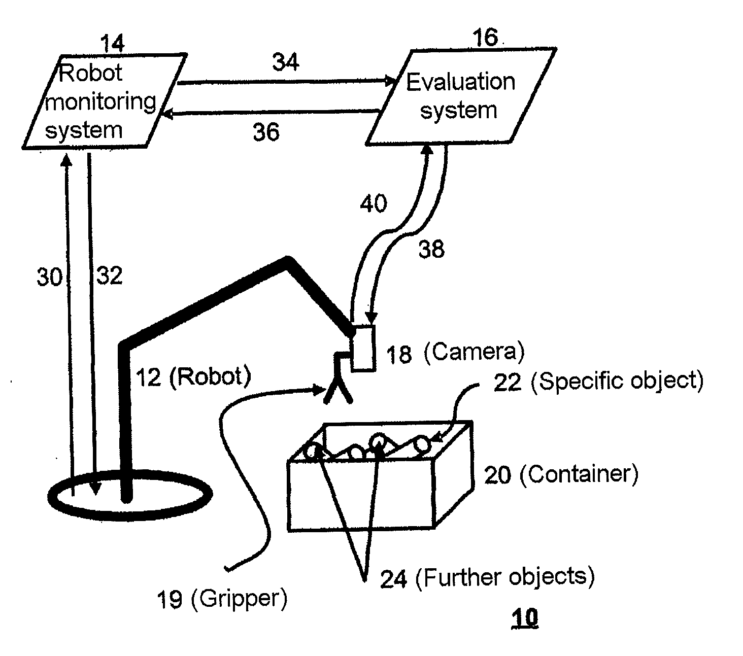
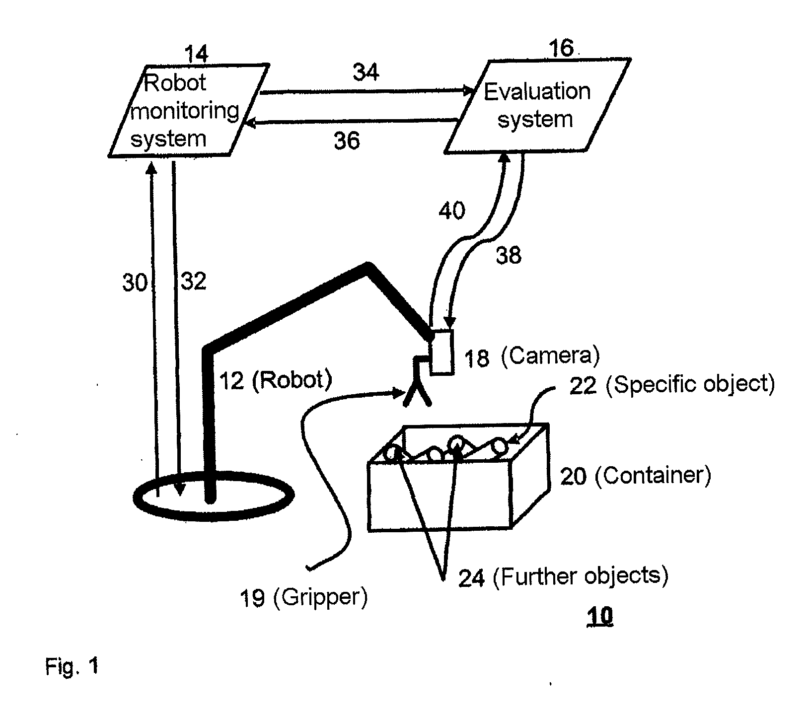
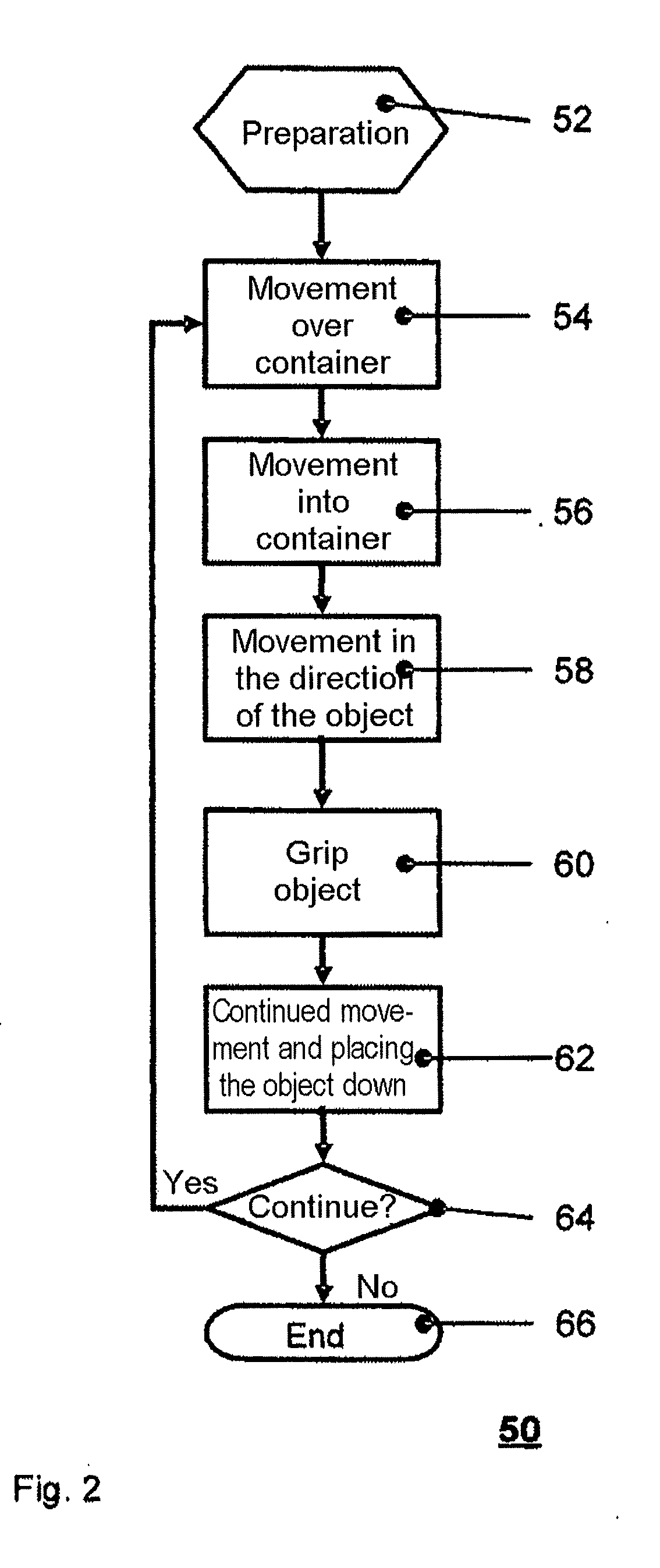
[0014]An exemplary method is disclosed for identifying the position of an object in three dimensions, which can use a single camera attached to the robot, and which can operate quickly.

[0015]An exemplary method determines the position of at least one specific object which is located within a working area of a robot, by an evaluation system, wherein a camera which is attached to the robot creates an image of at least a part of the working area of the robot.

[0016]The method includes creating an image during a movement of the camera. Image data can be supplied in real time to the evaluation system together with further data from which the position and / or orientation of the camera during creation of the image can be derived. The data can be used for position determination.

[0017]The creation of an image from the movement of the robot can avoid the time delay resulting from stopping the robot movement, and therefore advantageously speeds up the overall process of position determination.

[0...


PUM


Abstract

A method for determining the position of at least one object present within a working range of a robot by an evaluation system, wherein an image of at least one part of the working range of the robot is generated by a camera mounted on a robot. The image is generated during a motion of the camera and image data are fed to the evaluation system in real time, together with further data, from which the position and / or orientation of the camera when generating the image can be derived. The data are used for determining the position of the at least one object.

Description

RELATED APPLICATIONS[0001]This application claims priority as a continuation application under 35 U.S.C. §120 to PCT / EP2008 / 010517, which was filed as an International Application on Dec. 11, 2008 designating the U.S., and which claims priority to German Application 10 2007 060 653.4 filed in Germany on Dec. 15, 2007. The entire contents of these applications are hereby incorporated by reference in their entireties.FIELD[0002]The disclosure relates to a method for determining the position of at least one specific object, such as an object located within a working area of a robot. A camera is attached to the robot and can create an image of at least a part of the working area of the robot. In this context, the term object can refer to, for example, a work piece or an item which can be located in a loose state on a resting surface or in a container and is suitable for being picked up by a tool which is provided for this purpose.BACKGROUND INFORMATION[0003]It is known for images which ...

Claims


Application Information

Patent Timeline
IPC IPC(8): G05B15/00G06T7/00
CPCB25J9/1697G05B2219/37555G05B2219/40613G05B2219/40053G05B2219/40564G05B2219/39393
Inventor DAI, FAN
Owner ABB (SCHWEIZ) AG
Learn More