Cooling manifold and method for manufacturing the cooling manifold

a technology of cooling manifold and cooling manifold, which is applied in the direction of heat exchanger fastening, electrochemical generators, light and heating apparatus, etc., can solve the problem of not being able to maintain the battery cells within the desired temperature range of the air-cooled battery pack

Active Publication Date: 2010-11-04
LG ENERGY SOLUTION LTD
View PDF99 Cites 57 Cited by
  • Summary
  • Abstract
  • Description
  • Claims
  • Application Information

AI Technical Summary

Problems solved by technology

However, the typical air-cooled battery pack has a major challenge in maintaining a temperature of the battery pack within a desired temperat

Method used


Image

  • Cooling manifold and method for manufacturing the cooling manifold
  • Cooling manifold and method for manufacturing the cooling manifold
  • Cooling manifold and method for manufacturing the cooling manifold

Examples


Embodiment Construction

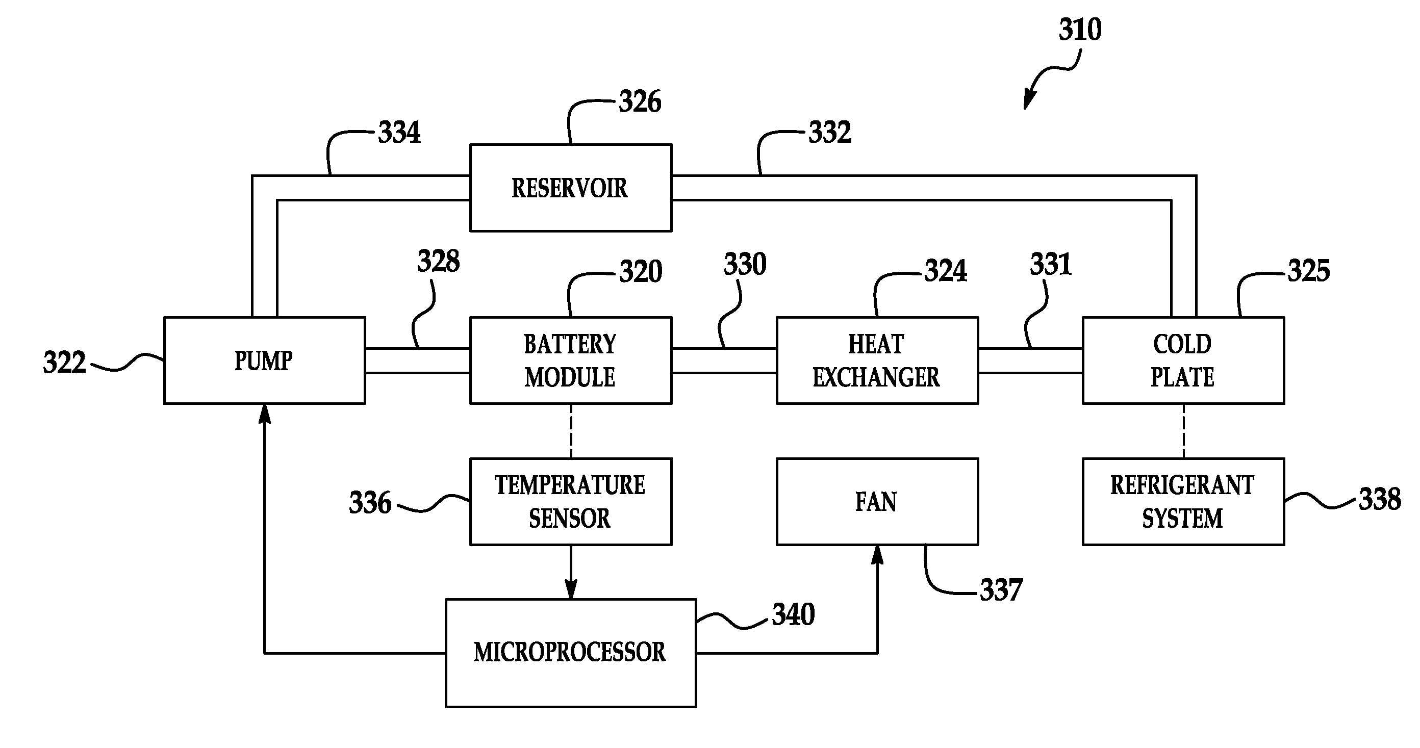
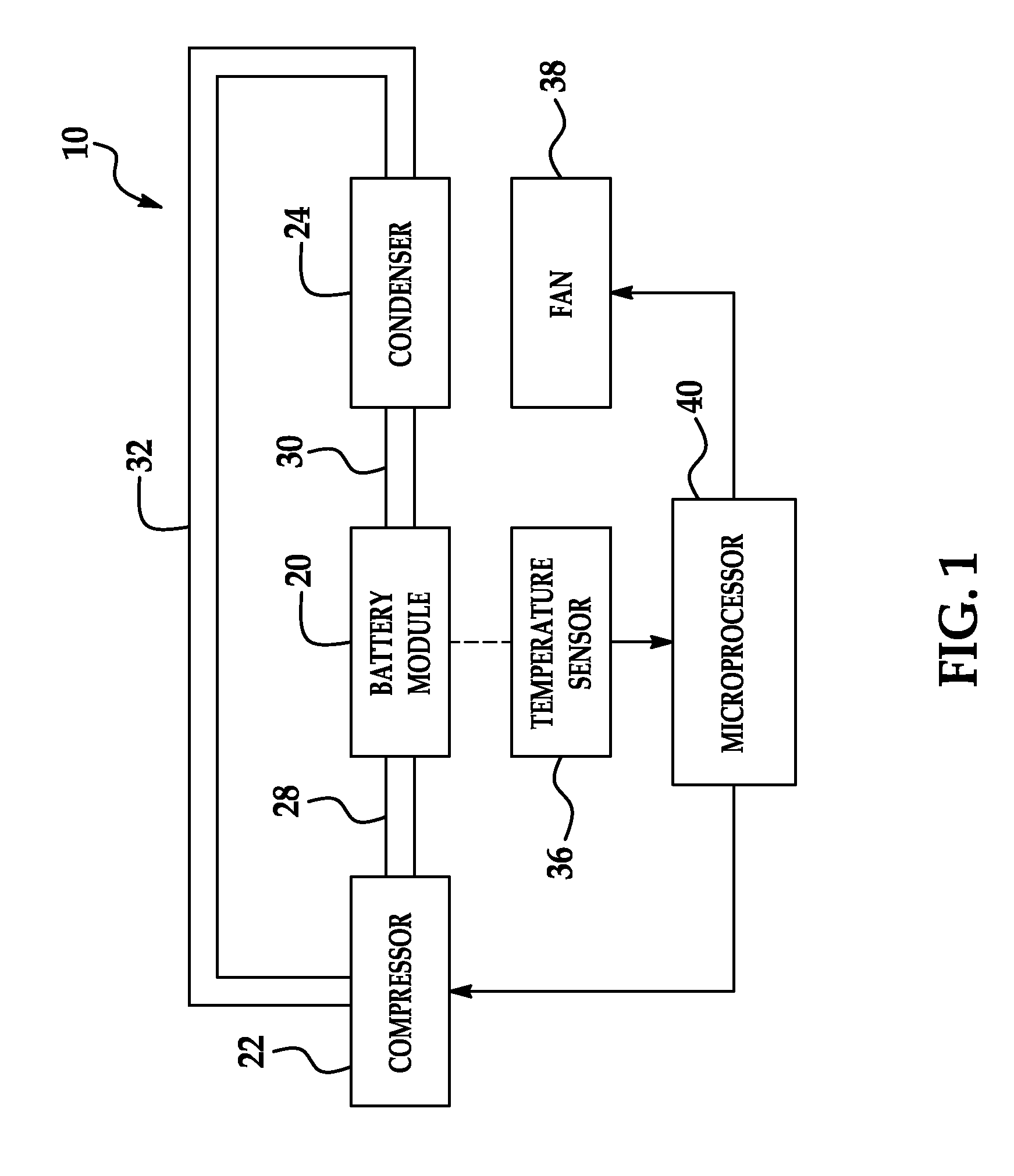
[0024]Referring to FIG. 1, a battery system 10 for generating electrical power in accordance with an exemplary embodiment is illustrated. The battery system 10 includes a battery module 20, a compressor 22, a condenser 24, conduits 28, 30, 32, a temperature sensor 36, a fan 38, and a microprocessor 40. An advantage of the battery module 20 is that the battery module utilizes graphite sheets and cooling manifolds conduct heat energy from battery cells in the battery module 20 to effectively cool the battery cells.

[0025]For purposes of understanding, the term “fluid” means either a liquid or a gas. For example, a fluid can comprise either a coolant or a refrigerant. Exemplary coolants include ethylene glycol and propylene glycol. Exemplary refrigerants include R-11, R-12, R-22, R-134A, R-407C and R-410A.

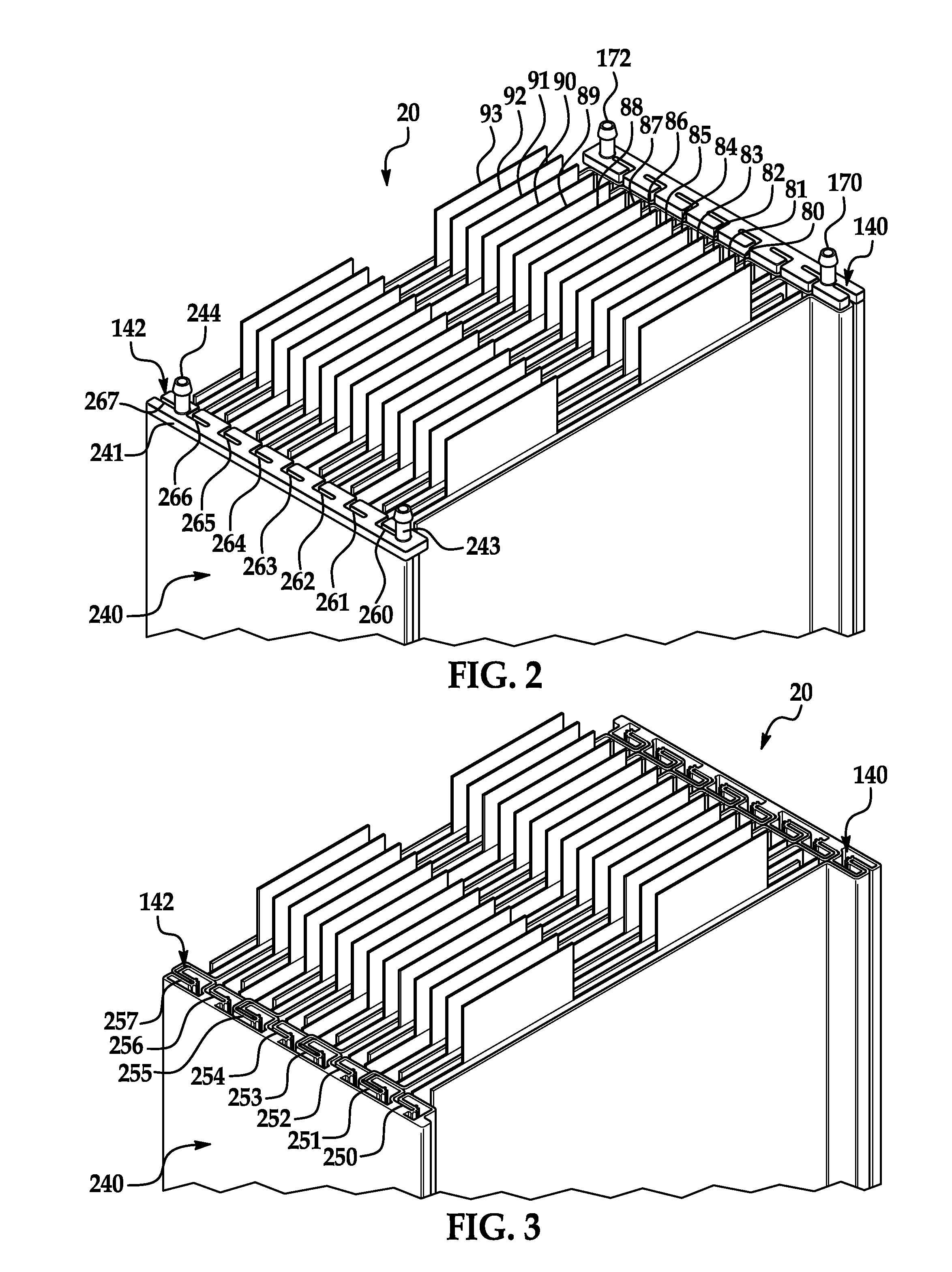
[0026]Referring to FIGS. 2-4, the battery module 20 is provided to generate a voltage therein in accordance with another exemplary embodiment. The battery module 20 includes battery ce...


PUM

PropertyMeasurementUnit
Flow rateaaaaaaaaaa
Electrical conductoraaaaaaaaaa
Energyaaaaaaaaaa

Abstract

A cooling manifold and a method for manufacturing the cooling manifold are provided. The cooling manifold includes a housing that defines an interior region having a serpentine flow path therein. The housing has a first plurality of grooves extending from a first surface of the housing into the housing. The grooves do not fluidly communicate with the interior region. The first plurality of grooves receive a portion of a thermally conductive member therein to conduct heat energy from the thermally conductive member to the housing. The cooling manifold further includes a top cap configured to seal a first end of the housing and a bottom cap configured to seal a second end of the housing.

Description

TECHNICAL FIELD[0001]This application relates to cooling manifold and a method for manufacturing the cooling manifold.BACKGROUND OF THE INVENTION[0002]In a typical air-cooled battery pack, ambient air from ambient atmosphere is directed across battery cells in the battery pack and is subsequently exhausted from the battery pack. However, the typical air-cooled battery pack has a major challenge in maintaining a temperature of the battery pack within a desired temperature range.[0003]In particular, a maximum operating temperature of the battery cells can often be less than a temperature of ambient air utilized to cool the batteries. In this situation, it is impossible to maintain the battery cells within a desired temperature range in an air-cooled battery pack.[0004]Accordingly, the inventors herein have recognized a need for an improved cooling manifold that minimizes and / or eliminates the above-mentioned deficiency.SUMMARY OF THE INVENTION[0005]A cooling manifold in accordance wit...

Claims


Application Information

Patent Timeline
IPC IPC(8): F28F3/12F28F9/22H05K7/20B23P15/26
CPCF28D15/0266F28F3/12F28F21/02H01M10/5004Y10T29/49389H05K7/20936F28F3/06F28F2275/14Y10T29/4935H01M10/5055H01M10/613H01M10/6555Y02E60/10
Inventor PAYNE, JOSH
Owner LG ENERGY SOLUTION LTD
Why Eureka
Try Eureka