
Material dispense tips and methods for forming the same

a technology of material dispense tips and nozzles, which is applied in the direction of liquid transferring devices, pliable tubular containers, instruments, etc., can solve the problems of material material drying up and clogging the material path, and difficulty in deburring the finished base, etc., to achieve the effect of low viscosity

Active Publication Date: 2010-11-04
DL TECH
View PDF99 Cites 11 Cited by
  • Summary
  • Abstract
  • Description
  • Claims
  • Application Information

AI Technical Summary

Benefits of technology

[0054]In accordance with another aspect, a dispense tip that communicates with a material dispensing pump comprises an elongated neck, a base, and a material path between an outermost region of the base and an outlet of the neck; the dispense tip formed according to the process...

Problems solved by technology

However, when conventional dispense tips are attached to a material dispensing pump, fluid material can leak from an interface between the base of the dispense tip and the pump due to the presence of imperfections such as nicks, cracks, burrs, protrusions, blemishes, dents, or other imperfections on the interfacing surface of the base or on the pump surface against which the base abuts.
However, these solvents can leach from the material and escape from cracks or crevices in the interfacing surface of the dispense tip, causing the material to dry up and clog the material path.
However, when machining these plastics from a stock, it is difficult to deburr the finished base from the stock, which can impede the flow of material in the material path formed by holes in the base and neck, or can clog the dispense tip.
Further, these plastics have high viscosity properties, which are undesirable for precision micromolding, since such plastics can be prone to imperfections when filling a mold during the molding process for forming the dispense tips.

Method used


Image

  • Material dispense tips and methods for forming the same
  • Material dispense tips and methods for forming the same
  • Material dispense tips and methods for forming the same

Examples


Embodiment Construction

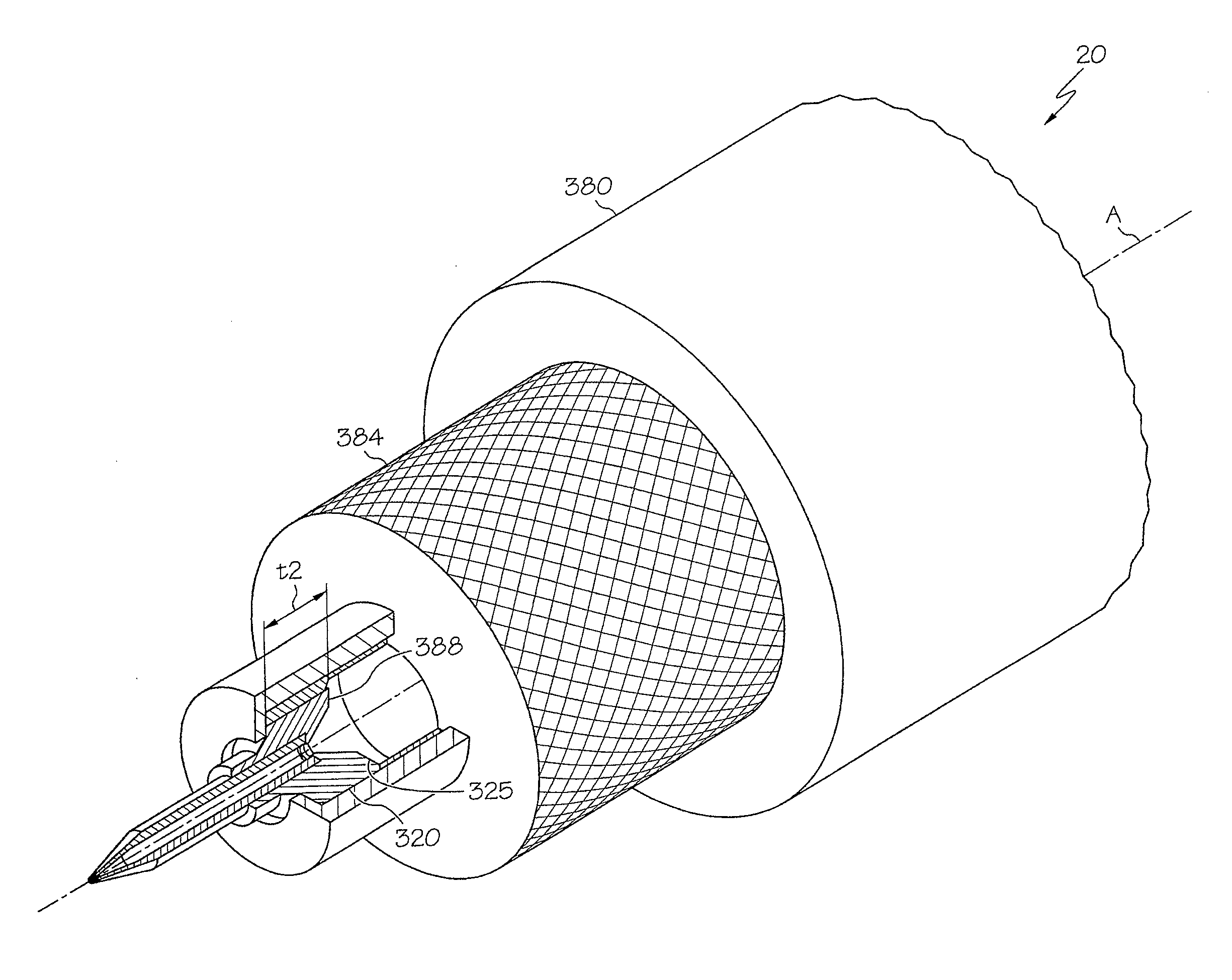
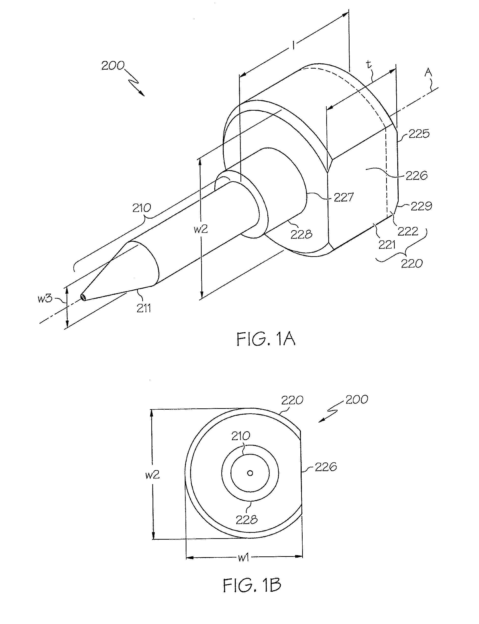
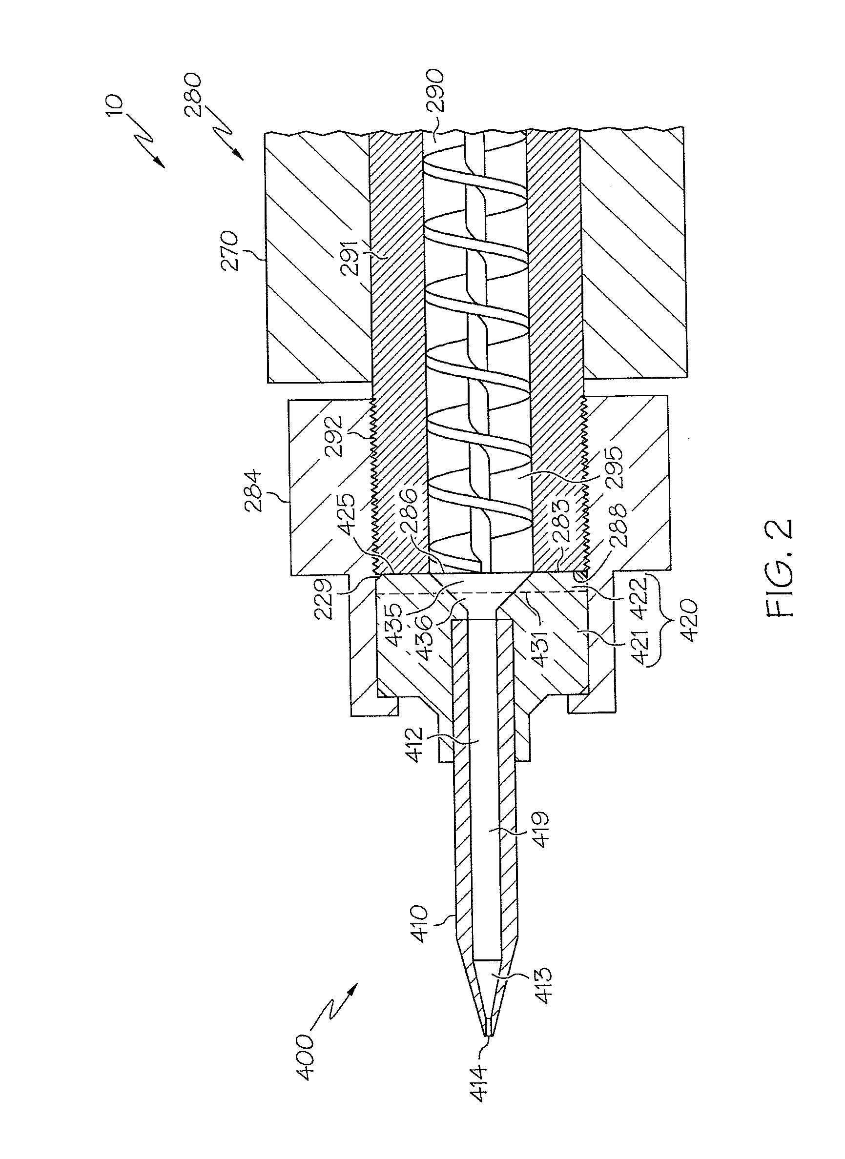
[0073]The accompanying drawings are described below, in which example embodiments in accordance with the present invention are shown. Specific structural and functional details disclosed herein are merely representative. This invention may be embodied in many alternate forms and should not be construed as limited to example embodiments set forth herein.

[0074]Accordingly, specific embodiments are shown by way of example in the drawings. It should be understood, however, that there is no intent to limit the invention to the particular forms disclosed, but on the contrary, the invention is to cover all modifications, equivalents, and alternatives falling within the spirit and scope of the claims.

[0075]It will be understood that, although the terms first, second, etc. may be used herein to describe various elements, these elements should not be limited by these terms. These terms are used to distinguish one element from another. For example, a first element could be termed a second elem...


PUM

PropertyMeasurementUnit
Volumeaaaaaaaaaa
Fractionaaaaaaaaaa
Timeaaaaaaaaaa

Abstract

A dispense tip constructed and arranged to communicate with a material dispensing pump comprises an elongated neck and a molded base having a first portion and a second portion opposite the first portion. The neck extends from the first portion of the base. The second portion is constructed and arranged to abut an outlet surface of the pump. An outermost region of the second portion of the base includes a compressible fluid-tight surface that compliantly conforms to the outlet surface when the dispense tip is mounted to the pump.

Description

RELATED APPLICATIONS[0001]This application claims the benefit of U.S. Provisional Patent Application No. 61 / 174,742 filed on May 1, 2009 and U.S. Provisional Patent Application No. 61 / 251,497 filed on Oct. 14, 2009, the entire contents of each of which are incorporated herein by reference.BACKGROUND OF THE INVENTION[0002]A material dispense tip, also referred to as a “pin” or “needle,” is utilized in a variety of applications. For example, a material dispense tip, when attached to a material dispensing pump system, is used to deposit a precise amount of fluid material, such as glue, resin, or paste, at precise positions on a semiconductor substrate. Examples of such material dispensing pumps are described in U.S. Pat. No. 6,511,301, U.S. Pat. No. RE 40,539, U.S. Pat. No. 6,892,959, U.S. Pat. No. 6,983,867, and U.S. Pat. No. 7,331,482, the contents of each of which are incorporated herein by reference in their entirety.[0003]A material dispense tip can be formed according to one of s...

Claims


Application Information

Patent Timeline
IPC IPC(8): B67D7/58B65D25/40B21D51/16
CPCB05C11/1034B05C17/00503Y10T29/4943Y10S239/12Y10S239/19G01F13/005B05B15/65B05B7/0466B05C17/00516B05B1/02B29C65/485B29K2063/00B29K2881/00B29L2031/7544
Inventor FUGERE, JEFFREY P.
Owner DL TECH
Learn More