Imaging Device
- Summary
- Abstract
- Description
- Claims
- Application Information
AI Technical Summary
Problems solved by technology
Method used
Image

Examples
example 1
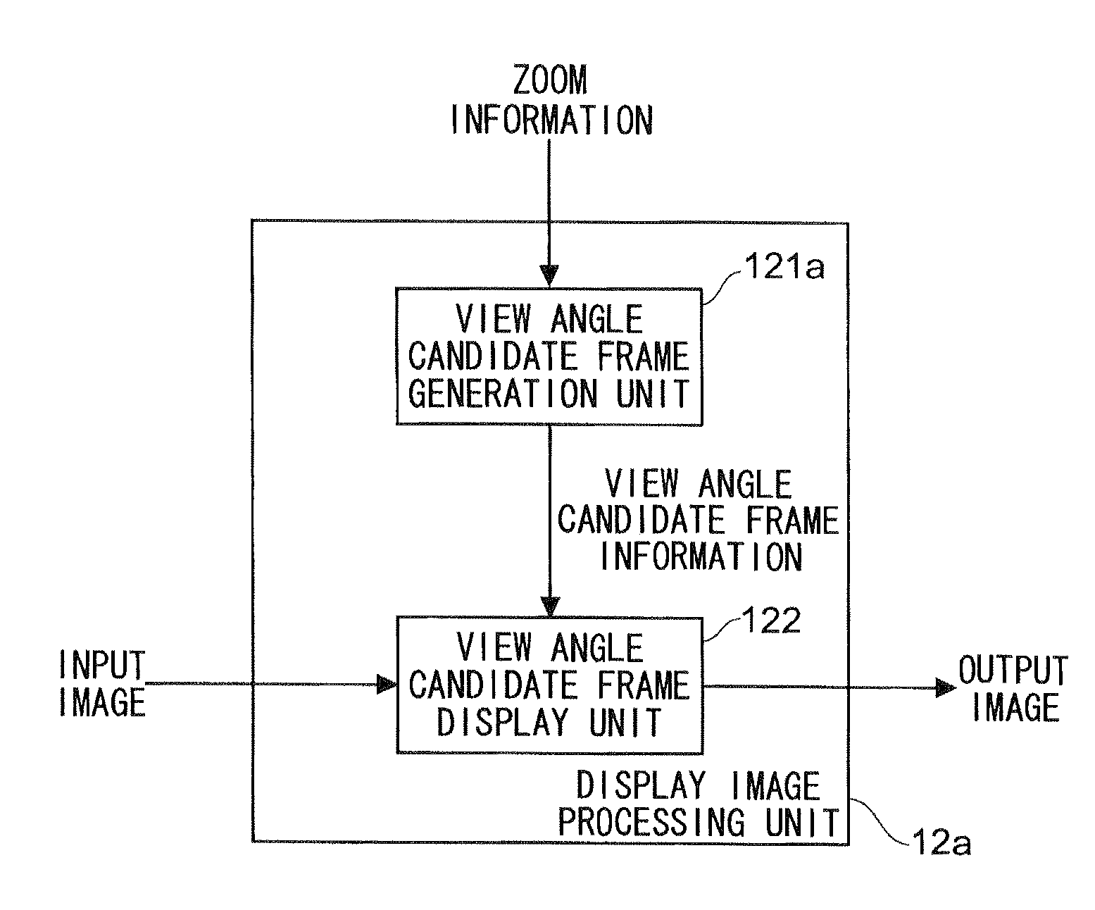
[0064]First, Example 1 of the display image processing unit 12 is described. FIG. 2 is a block diagram illustrating a configuration of Example 1 of the display image processing unit provided to the imaging device according to the embodiment of the present invention.
[0065]As illustrated in FIG. 2, a display image processing unit 12a of this example includes a view angle candidate frame generation unit 121a which generates view angle candidate frames based on zoom information and outputs the view angle candidate frames as view angle candidate frame information, and a view angle candidate frame display unit 122 which superimposes the view angle candidate frames indicated by the view angle candidate frame information on the input image so as to generate an output image to be output.
[0066]The zoom information includes, for example, information indicating a zoom magnification of the current setting (zoom magnification when the input image is generated) and information indicating limit val...
example 2
[0085]Example 2 of the display image processing unit 12 is described. FIG. 5 is a block diagram illustrating a configuration of Example 2 of the display image processing unit provided to the imaging device according to the embodiment of the present invention, which corresponds to FIG. 2 illustrating Example 1. Note that, in FIG. 5, parts similar to those in FIG. 2 illustrating Example 1 are denoted by similar names and symbols so that detailed descriptions thereof are omitted.
[0086]As illustrated in FIG. 5, a display image processing unit 12b of this example includes a view angle candidate frame generation unit 121b which generates the view angle candidate frames based on the zoom information and the object information, and outputs the same as view angle candidate frame information, and a view angle candidate frame display unit 122. This example is different from Example 1 in that the view angle candidate frame generation unit 121b generates the view angle candidate frames based on ...
first example
[0108]In a first example, the view angle candidate frames are generated by utilizing detection accuracy of the object (tracking reliability). First, an example of a method of calculating tracking reliability is described. Note that, as a method of detecting an object, the case where the detection is performed based on color information of the object (RGB or H of hue (H), saturation (S), and brightness (V)) is used are described as a specific example.
[0109]In the method of calculating the tracking reliability in this example, the input image is first divided into a plurality of small blocks, and the small blocks (object blocks) to which the object belongs and other small blocks (background blocks) are classified. For instance, it is considered that the background exists at a point sufficiently distant from the center point of the object. The classification is performed based on determination whether the pixels at individual positions between the points indicate the object or the back...
PUM
 Abstract
Description
Claims
Application Information
 - R&D Engineer
- R&D Manager
- IP Professional
- Industry Leading Data Capabilities
- Powerful AI technology
- Patent DNA Extraction
Browse by: Latest US Patents, China's latest patents, Technical Efficacy Thesaurus, Application Domain, Technology Topic.
© 2024 PatSnap. All rights reserved.Legal|Privacy policy|Modern Slavery Act Transparency Statement|Sitemap