Apparatus for detecting a pointer within a region of interest

a pointer and object technology, applied in the field of interactive systems, can solve the problems of increasing the cost of monochrome digital cameras to capture images, reducing the ability to determine the existence of a pointer in captured image data, and increasing the cost of manufacturing costs, so as to achieve the effect of increasing the information of pointer attributes and being convenient to obtain

Active Publication Date: 2007-06-19
SMART TECH INC (CA)
View PDF88 Cites 246 Cited by
  • Summary
  • Abstract
  • Description
  • Claims
  • Application Information

AI Technical Summary

Benefits of technology

[0034]at least one filter changing the frequency band of light in a cycle thereby to enable said imaging devices to capture images looking across said region of interest in different lighting conditions.
[0035]The present invention provides advantages in that in one embodiment, backlight illumination is provided across the touch surface in an effective and cost efficient manner. The present invention provides further advantages in that since images looking across the region of interest can be acquired at different frequency bands of light, in addition to determining the location of the pointer, increased pointer attribute information can be easily obtained.

Problems solved by technology

Although this camera-based touch system works extremely well, it has been found that when the digital camera frame rates are high, in less favorable light conditions, the ability to determine the existence of a pointer in the captured image data is diminished.
Although the illuminated bezel works very well, because the illuminated bezel completely surrounds the touch surface and makes use of an array of infrared light emitting diodes mounted on a printed circuit board that is disposed behind a diffuser, manufacturing costs are significant especially in cases where the illuminated bezel surrounds large touch surfaces.
Also, although the existence of the pointer in captured images can be readily detected, currently the use of monochrome digital cameras to capture images increases costs and provides limited information concerning attributes of the pointer used to contact the touch system.

Method used


Image

  • Apparatus for detecting a pointer within a region of interest
  • Apparatus for detecting a pointer within a region of interest
  • Apparatus for detecting a pointer within a region of interest

Examples


Embodiment Construction

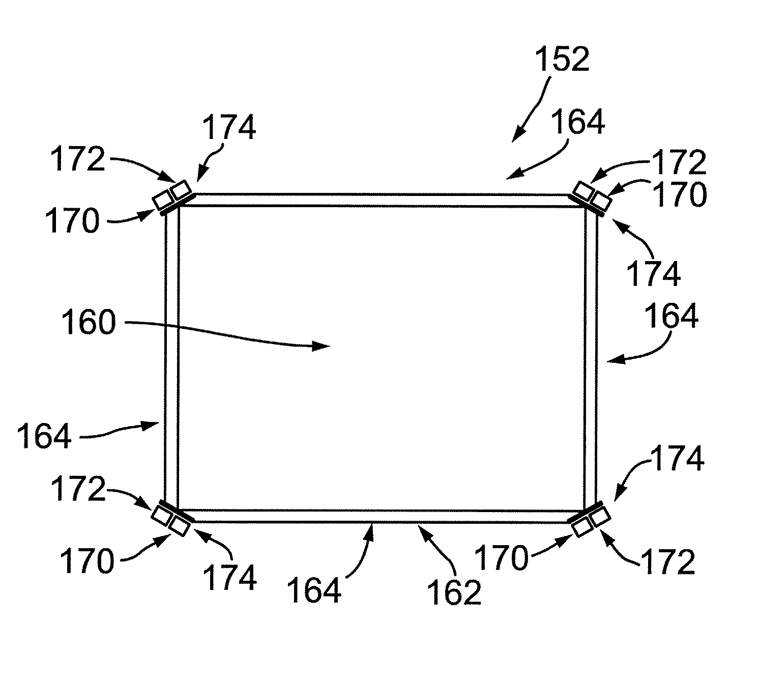
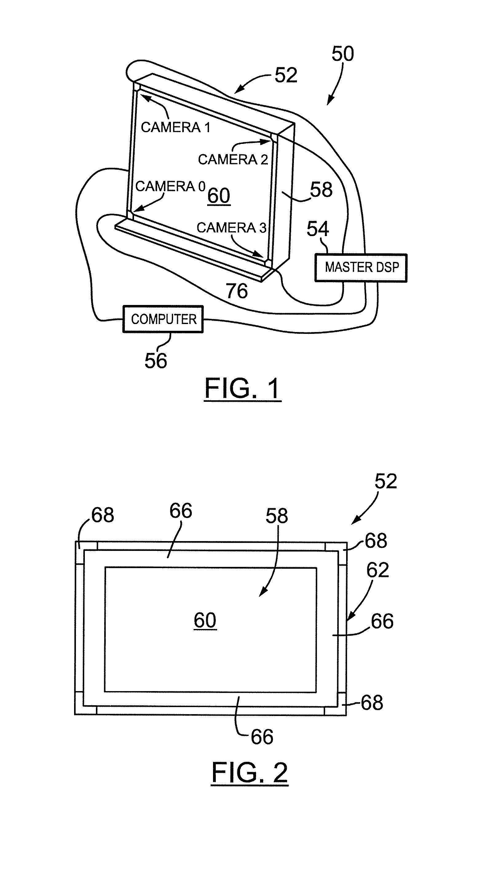
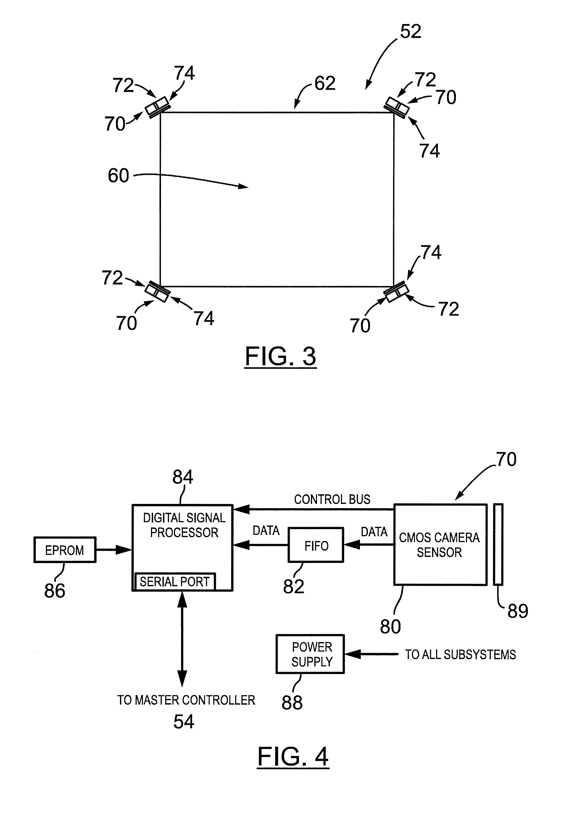
[0045]Turning now to FIGS. 1 to 3, an apparatus for detecting a pointer within a region of interest in accordance with the present invention is shown and is generally identified by reference numeral 50. In this embodiment, apparatus 50 is a camera-based touch system similar to that disclosed in International PCT Application Serial No. WO 02 / 03316, assigned to SMART Technologies Inc., assignee of the present invention, the content of which is incorporated herein by reference. As can be seen, touch system 50 includes a touch screen 52 coupled to a digital signal processor (DSP) based master controller 54. Master controller 54 is also coupled to a computer 56. Computer 56 executes one or more application programs and generates computer-generated image output that is presented on the touch screen 52. The touch screen 52, master controller 54 and computer 56 form a closed-loop so that pointer contacts made on the touch screen 52 can be recorded as writing or drawing or used to control ex...


PUM


Abstract

An apparatus for detecting a pointer within a region of interest includes at least one pair of imaging devices. The imaging devices have overlapping fields of view encompassing the region of interest. At least one light source provides illumination across the region of interest and is within the field of view of at least one of the imaging device. A filter is associated with the at least one imaging device whose field of view sees the light source. The filter blocks light projected by the light source to inhibit the imaging device from being blinded by the projected light.

Description

FIELD OF THE INVENTION [0001]The present invention relates generally to interactive systems and in particular to an apparatus for detecting a pointer within a region of interest.BACKGROUND OF THE INVENTION[0002]Touch systems are well known in the art and typically include a touch screen having a touch surface on which contacts are made using a pointer such as for example a pen tool, finger or other suitable object. Pointer contacts with the touch surface are detected and are used to generate output pointer position data representing areas of the touch surface where pointer contacts are made.[0003]International PCT Application No. PCT / CA01 / 00980 filed on Jul. 5, 2001 and published under number WO 02 / 03316 on Jan. 10, 2002, assigned to SMART Technologies Inc., assignee of the present invention, discloses a passive camera-based touch system. The camera-based touch system comprises a touch screen that includes a touch surface on which a computer-generated image is presented. A rectangul...

Claims


Application Information

Patent Timeline
Patent Type & Authority Patents(United States)
IPC IPC(8): G06M7/00G09G5/00G06F3/042
CPCG06F3/0421G02B5/124
Inventor WORTHINGTON, STEPHENMORRISON, GERALD D.GURTLER, PATRICK JAMES
Owner SMART TECH INC (CA)
Why Eureka
Try Eureka