Vessel Position and Configuration Imaging Apparatus and Methods

a configuration imaging and vessel technology, applied in the field of prosthesis deployment, can solve the problems of weakened abnormal dilated walls, increased risk of entanglement of these components, and increased complexity of procedures

Active Publication Date: 2008-07-17
MEDTRONIC VASCULAR INC
View PDF98 Cites 252 Cited by
  • Summary
  • Abstract
  • Description
  • Claims
  • Application Information

AI Technical Summary

Benefits of technology

[0017]In another embodiment according to the invention, a method of real time monitoring the position of a portion of a second vessel, which branches from a first vessel in a human patient comprises positioning a trackable marker (e.g., an electromagnetic coil) in a second vessel, which branches from a first vessel in a human patient; subjecting the marker to non-ionizing radiation energy (e.g., generating electromagnetic fields about the coil); and processing the marker's response to or effect on the non-ionizing energy (e.g., processing signals from an electromagnetic coil marker in response to electromagnetic field generation thereabout) to determine the position of the marker.
[0018]In another embodiment according to the invention, a method of real time virtual three-dimensional modeling of a vessel comprises positioning each of a plurality of trackable markers (e.g., electromagnetic coils) against the inner wall of a vessel; subjecting the markers to non-ionizing radiation energy (e.g., generating electromagnetic fields about the markers); and processing the markers' response to or effect on the non-ionizing radiation (e.g. processing signals from electromagnetic coil markers in response to electromagnetic field generation thereabout) to create a virtual three-dimensional model of a portion of the vessel inner wall.
[0019]In another embodiment according to the invention, a method of generating a representation generally along the central axis of a portion of a vessel comprises positioning a plurality of markers in a vessel in a configuration that has an axis that extends generally along the central axis of a portion of the vessel; subjecting the markers to non-ionizing radiation energy; and generating a virtual three-dimensional model of the configuration axis that extends generally along the central axis of a portion of the vessel based on the markers' response to or effect on the non-ionizing radiation energy.

Problems solved by technology

The abnormally dilated wall typically is weakened and susceptible to rupture.
Although the endovascular approach is much less invasive, and usually requires less recovery time and involves less risk of complication as compared to open surgery, there can be concerns with alignment of asymmetric features of various prostheses in relatively complex applications such as one involving branch vessels.
The procedure becomes more complicated when more than one branch vessel is treated.
One example is when an aortic abdominal aneurysm is to be treated and its proximal neck is diseased or damaged to the extent that it cannot support a patent connection with a prosthesis.
Not only is there risk of entanglement of these components, a standard off the shelf prosthesis with pre-formed fenestrations may not properly align with the branch vessels due to differences in anatomy from one patient to another.
A custom prostheses having preformed fenestrations or openings based on a patient's CAT scans also is not free from risk.
A custom prosthesis is still subject to a surgeon's interpretation of the scan and may not result in the desired anatomical fit.
When the vessel is reshaped by an outside force such as a stiff catheter, even a custom designed prosthesis may not properly align with the branch vessels.
Generally speaking, one challenge in prosthesis (e.g., stent-graft) delivery / placement in the vicinity of one or more branch vessels is identifying and locating the position of branch vessels (e.g., arteries).
For example, this challenge exists whether the distal end of the prosthesis is to be positioned below or above the renal arteries.
Although fluoroscopy has been used to identify branch vessels such as the renal arteries for assisting in prosthesis positioning, there remain challenges with this approach.
While physicians always try to use low dose rates during fluoroscopy, the length of a procedure may be such that it results in a relatively high absorbed dose to the patient.

Method used


Image

  • Vessel Position and Configuration Imaging Apparatus and Methods
  • Vessel Position and Configuration Imaging Apparatus and Methods
  • Vessel Position and Configuration Imaging Apparatus and Methods

Examples


example 1

[0088]Referring to FIGS. 9A-E, an exemplary operation of system 100 where the tracked elements or markers used are sensing coils and more specifically electromagnetic field (EMF) coils will now be described. For the purposes of the example, the procedure involves the endovascular delivery and deployment of an AAA bifurcated stent-graft in the vicinity of the renal arteries. In the example described below, the procedure can be performed using a preprocedural or intraoperative scan of the vasculature being navigated to generate a three-dimensional model of the navigational path. An exemplary preprocedural scan approach will be described first and an intraoperative scan approach will follow.

Pre-procedural or Preoperative Scan

[0089]First or pre-procedural scan and aortic data acquisition: Prior to the surgical procedure, the patient is scanned using either a CT, CTA, MRI, or MRA scanner to generate a three-dimensional model of the vasculature to be tracked. The abdominal aorta and branc...

example 2

[0118]Referring to FIGS. 10A and 10B, a procedure for locating vessels for prosthesis deployment using system 200 where the tracked elements or markers used are sensing coils and more specifically electromagnetic field (EMF) coils will now be described. For the purposes of the example, the procedure involves the endovascular delivery and deployment of an AAA bifurcated stent-graft in the vicinity of the renal arteries.

[0119]As described above, the patient is prepared for surgery and a cut is made down to a femoral artery and elongated members 302 and 402 are endovascularly advanced toward the renal arteries and their distal portions positioned in the renals using conventional fluoroscopic techniques (FIG. 10A).

[0120]While viewing the fluoroscopic image of the renals and tracked elements or markers 306c and 406c, the markers or sensing coils are aligned with a lower portion of a respective ostium of the renal arteries generally indicated with BV1 and BV2.

[0121]In one variation, after...

example 3

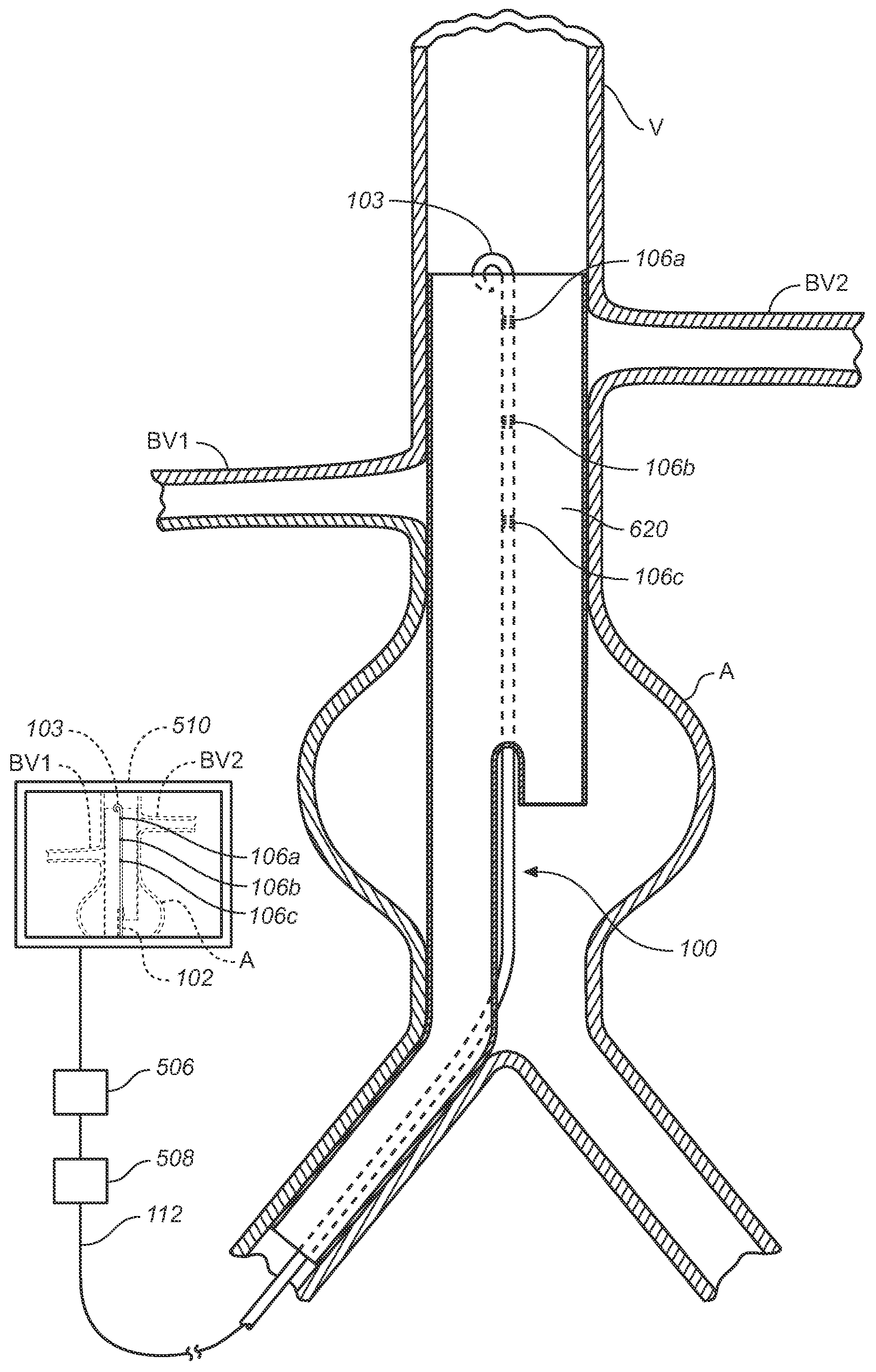
[0139]Referring to FIGS. 15A-C, an exemplary operation of system 800 where electromagnetic coil type tracked elements or markers are used in conjunction with circuit 500 and puncture catheter 1110 will now be described. For the purposes of the example, the procedure involves the endovascular delivery and deployment of an AAA bifurcated stent-graft in the superior to a renal artery.

[0140]Elongated member of catheter 802 is endovascularly advanced from a femoral artery as described above into a branch vessel BV1, which in this example is a renal artery, using conventional fluoroscopic technique. Sheath 805 is withdrawn allowing the distal end 803 to move toward its memory shape helical configuration. As it moves toward its helical configuration the sensor coils are moved toward and / or urged against the inner wall of the branch artery and generally positioned in a helical array (FIG. 15A) about axis A1-A1, which generally corresponds to the center axis of that portion of the artery. Ty...


PUM


Abstract

One or more markers or sensors are positioned in the vasculature of a patient to facilitate determining the location, configuration, and/or orientation of a vessel or certain aspects thereof (e.g., a branch vessel), determining the location, configuration and/or orientation of a endovascular devices prior to and during prosthesis deployment as well as the relative position of portions of the vasculature and devices, generating an image of a virtual model of a portion of one or more vessels (e.g., branch vessels) or devices, and/or formation of one or more openings in a tubular prosthesis in situ to allow branch vessel perfusion when the prosthesis is placed over one or more branch vessels in a patient (e.g., when an aortic abdominal artery stent-graft is fixed to the aorta superior to the renal artery ostia).

Description

FIELD OF THE INVENTION[0001]The invention relates to prosthesis deployment and more particularly to locating a branch passageway in a human body such as a branch artery prior to prosthesis deployment or locating a passageway in a prosthesis prior to in-vivo cannulation thereof.BACKGROUND OF THE INVENTION[0002]Tubular prostheses such as stents, grafts, and stent-grafts (e.g., stents having an inner and / or outer covering comprising graft material and which may be referred to as covered stents) have been widely used in treating abnormalities in passageways in the human body. In vascular applications, these devices often are used to replace or bypass occluded, diseased or damaged blood vessels such as stenotic or aneurysmal vessels. For example, it is well known to use stent-grafts, which comprise biocompatible graft material (e.g., Dacron® or expanded polytetrafluoroethylene (ePTFE)) supported by a framework (e.g., one or more stent or stent-like structures), to treat or isolate aneury...

Claims


Application Information

Patent Timeline
Patent Type & Authority Applications(United States)
IPC IPC(8): A61B5/05A61F11/00A61F2/06
CPCA61B5/06A61M2025/0166A61B19/52A61B19/5244A61B2017/003A61B2017/00867A61B2019/505A61B2019/507A61B2019/5251A61B2562/0209A61B2562/043A61F2/07A61F2/954A61F2002/061A61F2002/065A61F2250/0002A61F2250/0096A61M25/007A61M25/0108A61B5/6857A61B90/36A61B34/20A61B2034/105A61B2034/107A61B2034/2051A61B5/062
Inventor GREENAN, TREVORYAMASAKI, DWAYNE S.BRUSZEWSKI, WALTERGARDESKI, KENSIMON, DAVID
Owner MEDTRONIC VASCULAR INC
Why Eureka
Try Eureka