Needle Assembly with Removable Depth Stop

a bone needle and stop technology, applied in the field of medicine, can solve the problems of affecting the accuracy of the needle assembly, requiring simultaneous exercise of substantial force and precision, and not fully meeting the need for variability in the length of the needl

Active Publication Date: 2010-11-04
CARDINAL HEALTH IRELAND UNLTD
View PDF102 Cites 30 Cited by
  • Summary
  • Abstract
  • Description
  • Claims
  • Application Information

AI Technical Summary

Benefits of technology

[0007]In one aspect of the present invention, a convertible needle assembly generally comprises a mounting structure and a needle having a longitudinal axis and a sharp end, the needle being mounted on the mounting structure and projecting outwardly from the mounting structure so that the sharp end is generally remote from the mounting structure. A depth stop adapted to limit the depth of penetration of the needle is releasably connected by a rotary connector to the needle assembly. The released depth stop is removable from the needle for increasing the possible depth of penetration of the needle.
[0008]In another aspect of the present invention, a bone needle assembly generally comprises a handle and a needle having a longitudinal axis and a sharp end. The needle is mounted on the handle at a location away from the sharp end of the needle and projects outwardly from the handle. A depth stop unit comprises a positioning stem and a depth stop mounted on the position stem and movable along a length of the stem to different selected positions along the stem and along the longitudinal axis of the needle. The depth stop has a stop surface adapted to limit the depth of penetration of the needle. A rotary connector of the depth stop unit is adapted to releasably connect the stem to the needle assembly. The rotary connector is capable of releasing connection of the stem so that the stem and depth stop may be removed from the needle for increasing the possible depth of penetration of the needle.

Problems solved by technology

However, there are also situations where the needle has to penetrate a substantial distance through tissue in order to inject a drug or withdraw fluid.
For example, if the needle penetrates too deeply, it could damage an untargeted area of the body.
Thus, the use of a bone needle assembly of this type requires the simultaneous exercise of substantial force and precision.
While these adjustable depth stop units provide greater flexibility they do not fully meet the need for variability in needle length.
In instances where a depth stop is present in the needle assembly, a substantial length of the needle will never be available for use to penetrate into the body because it will remain covered by the depth stop.

Method used


Image

  • Needle Assembly with Removable Depth Stop
  • Needle Assembly with Removable Depth Stop
  • Needle Assembly with Removable Depth Stop

Examples


Embodiment Construction

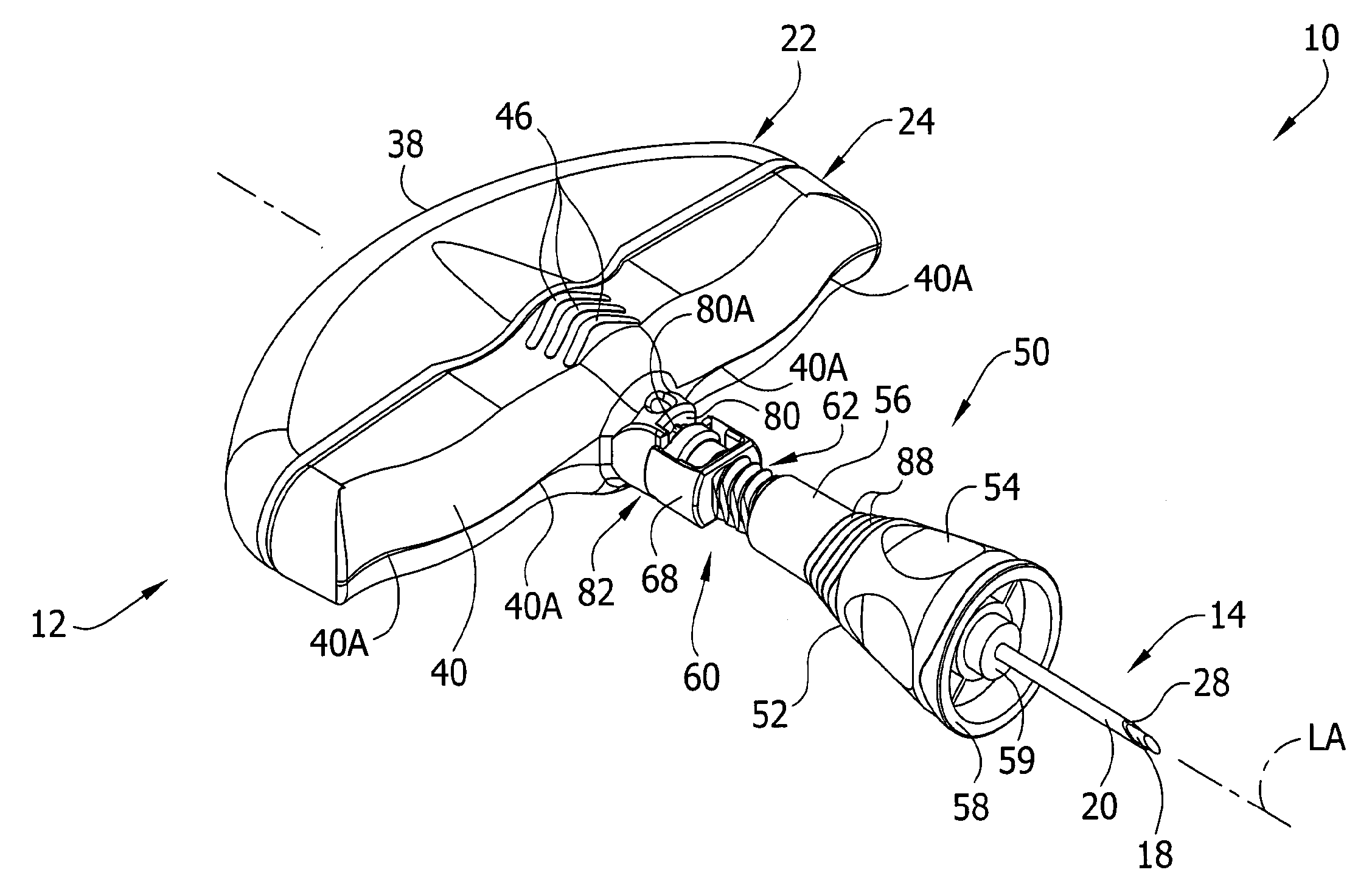
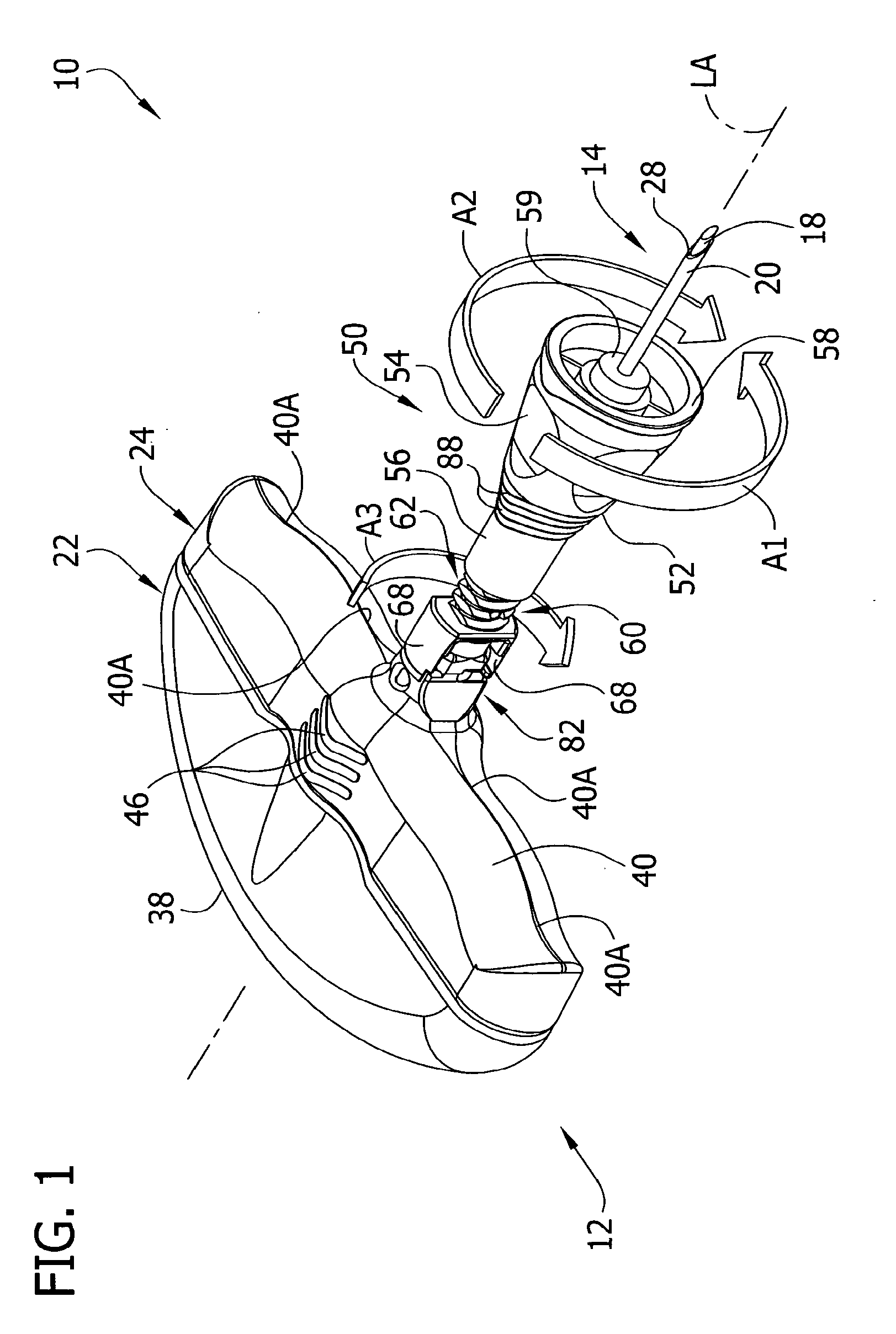
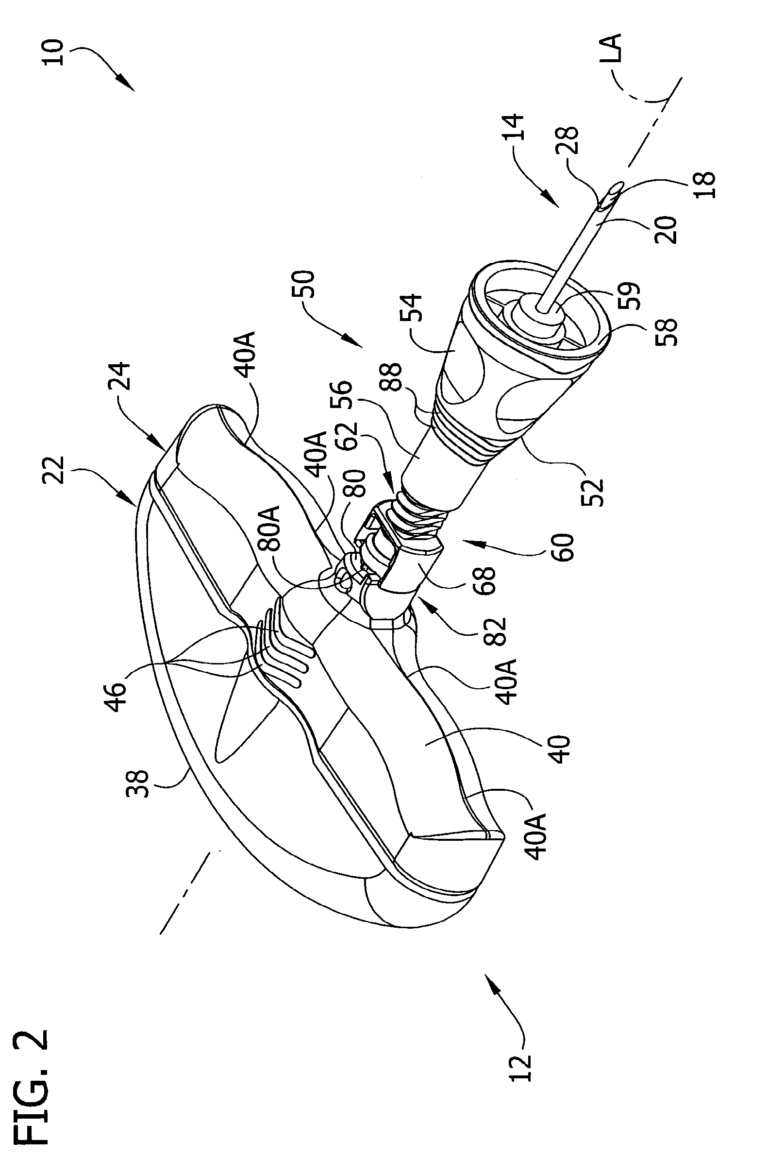
[0021]Referring now to the drawings and in particular to FIGS. 1-3, a bone needle assembly constructed according to the principles of the present invention is indicated generally at 10. The bone needle assembly includes a handle 12 (broadly, “mounting structure”), and a needle 14, all reference numbers indicating their subjects generally. The needle 14 includes a stylet 18 and a cannula 20 that can receive the stylet. The handle 12 includes a first or proximal handle member (indicated generally at 22) mounting the stylet 18, and a second or distal handle member (indicated generally at 24) mounting the cannula 20. “Proximal” and “distal” refer to the relative location of the handle members to a medical technician when the needle assembly is in use. The proximal handle member 22 is in contact with the palm of the technician's hand in use, and the distal handle member 24 is on the opposite side of the proximal handle member from the palm. It will be understood that a needle could inclu...


PUM


Abstract

A needle assembly (10) includes a needle (14) attached to mounting structure (12), and is used to insert the needle into the body of a patient. A depth stop unit (50) of the needle assembly provides a stop surface (58) to limit the distance the needle can be inserted into the body. The depth stop unit may include a depth stop (52) that is adjustable to selectively change the depth to which the needle can be inserted. The entire depth stop unit can be removed from the needle assembly to permit the full length of the needle to penetrate into the body.

Description

CROSS REFERENCE TO RELATED APPLICATION[0001]This application includes subject matter in common with co-assigned U.S. patent application Ser. No. ______, entitled Bayonet Release of Safety Shield for Needle Tip, filed simultaneously herewith. The subject matter of this application is incorporated herein in its entirety by reference.BACKGROUND OF THE INVENTION[0002]This invention relates generally to needles used in medicine and more particularly to a needle assembly having a depth stop to limit penetration of the needle into the subject, which depth stop can be selectively removed from the needle.[0003]In some medical applications needles are used to make relatively deep penetrations into the body in order to perform their tasks. For instance where it is necessary to obtain a biopsy sample, the needle may have to penetrate deep inside tissue to the location from which the sample is to be taken. However, there are also situations where the needle has to penetrate a substantial distanc...

Claims


Application Information

Patent Timeline
Patent Type & Authority Applications(United States)
IPC IPC(8): A61M5/46A61B10/02
CPCA61B2019/306A61B10/025A61B2090/036A61B17/34A61M5/162A61M25/06
Inventor MOOS, KIMBERLY A.SWISHER, DAVID RORKREYNOLDS, WHITNEY
Owner CARDINAL HEALTH IRELAND UNLTD
Why Eureka
Try Eureka