Fiber texture for a casing made of composite material with improved impact resistance

a composite material and impact resistance technology, applied in the field of fiber texture, can solve the problems of high deformation rate, high mechanical properties, and third function of the casing material, and achieve the effects of good rigidity, and reducing the impact of us

Pending Publication Date: 2021-09-23
SAFRAN +1
View PDF0 Cites 0 Cited by
  • Summary
  • Abstract
  • Description
  • Claims
  • Application Information

AI Technical Summary

Benefits of technology

[0026]Thereby, this limits the depth of penetration of a projectile, for example a blade or a blade portion, impacting the inner surface of the casing. Thereby, this preserves a larger portion of the casing material, which allows effectively ensuring the management of the phases described above (in particular phases 3 to 5) during a blade-out event or blade fraction.
[0029]In one exemplary embodiment, layers of the plurality of layers of weft yarns or strands present in the first section on the side of an inner face of the fibrous texture include or consist of a plurality of groups of yarns or strands each comprising at least one carbon fiber yarn or strand and one glass fiber yarn or strand, the other layers of weft yarns or strands present on the side of an outer face of the fibrous texture consisting of or including carbon fiber yarns or strands of. This allows maintaining good rigidity in this first section and limiting the impact of the use of glass fiber yarns or strands, these having a greater mass than the carbon fiber yarns or strands.
[0030]In one exemplary embodiment, the first section of the fibrous texture includes a retention portion extending set back from the lateral edges of said fibrous structure along the lateral direction, the retention portion comprising a greater number of glass fiber yarns or strands than in the portions adjacent to the retention portion along the lateral direction. The retention portion is intended to be present facing the blades and defines the retention area of the casing to be obtained. This retention area of the casing has the function of retaining the debris, particles or objects ingested at the inlet of the engine, or the blades or blade fragments detached and projected radially by centrifugation against the casing. Thus, the glass fiber yarns or strands whose mass is greater than that of the carbon fiber yarns or strands are concentrated in the area likely to be impacted by a projectile, particularly a blade or a blade fragment. Thereby, this lightens the overall mass of the casing.

Problems solved by technology

On the other hand, the third function, even if it is used very little, is very demanding in terms of mechanical properties.
During this phase, a high rate of deformation is required from the material of the casing.

Method used


Image

  • Fiber texture for a casing made of composite material with improved impact resistance
  • Fiber texture for a casing made of composite material with improved impact resistance
  • Fiber texture for a casing made of composite material with improved impact resistance

Examples


Embodiment Construction

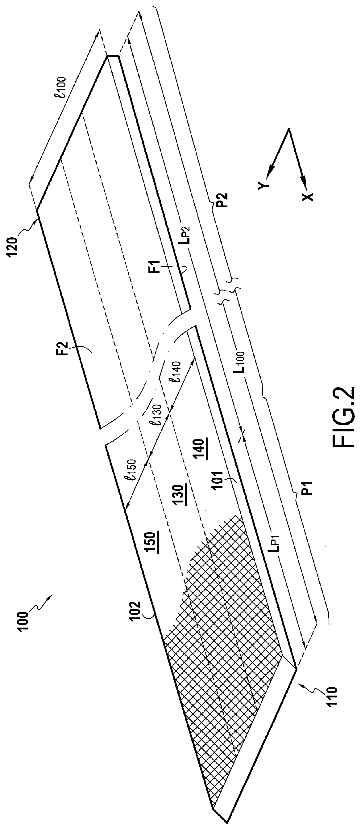
[0048]The invention generally applies to fibrous textures intended for the manufacture of casings made of composite material, these casings including a barrel or a shroud with annular clamps at their ends.

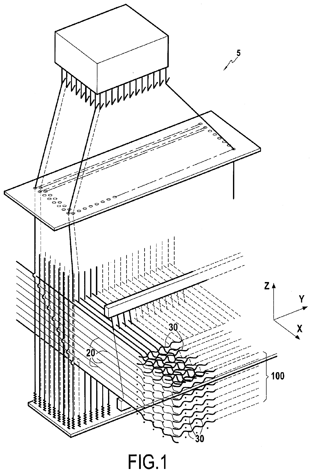
[0049]As represented in FIG. 1, a fibrous texture 100 is produced in a known manner by weaving by means of a jacquard-type loom 5 on which a bundle of warp yarns or strands 20 has been disposed in a plurality of layers, the warp yarns being interlinked by weft yarns or strands 30.

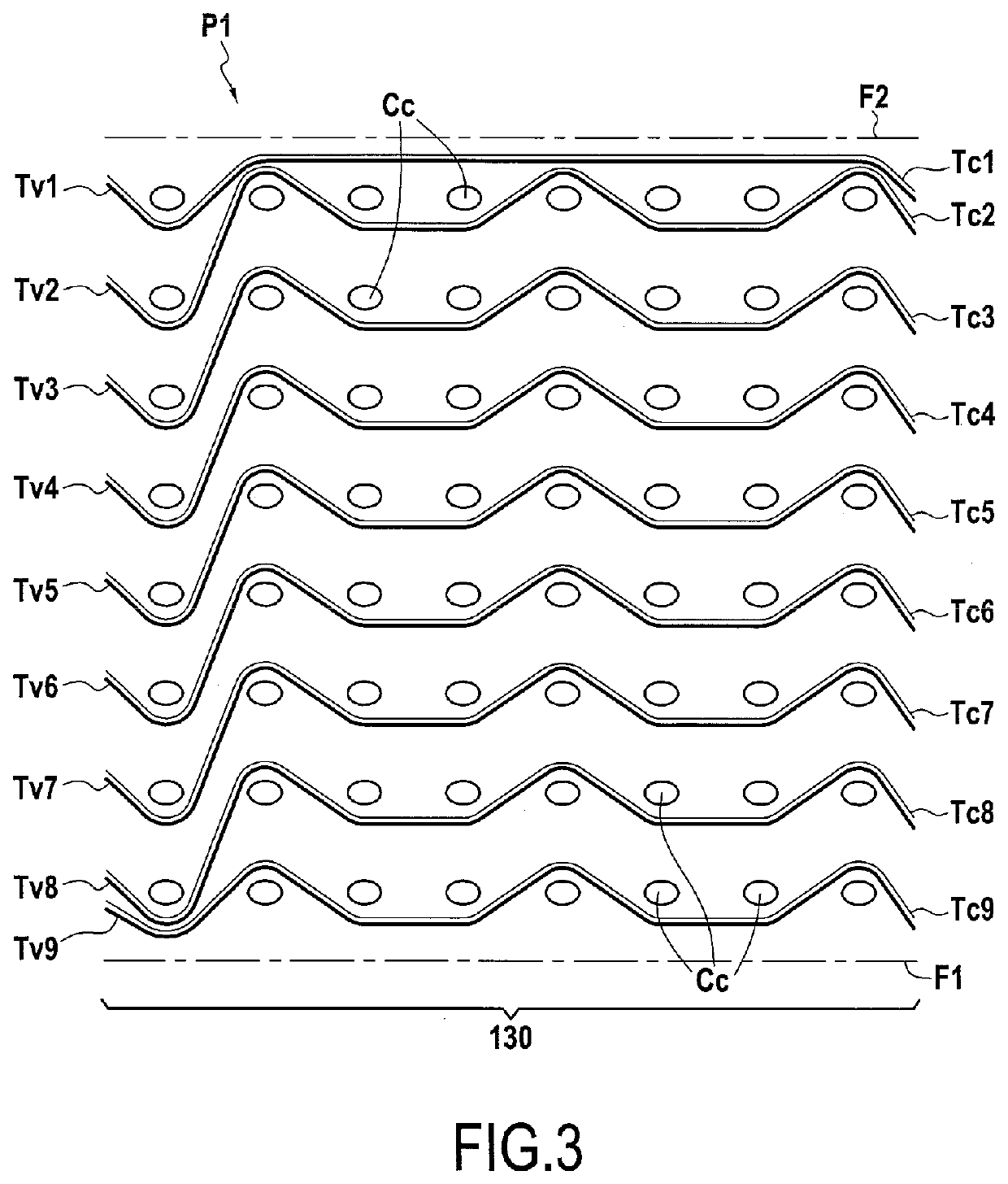
[0050]The fibrous texture is produced by three-dimensional weaving. By “three-dimensional weaving” or “3D weaving” is meant here a weaving mode by which at least some of the weft yarns interlink warp yarns on several layers of warp yarns or vice versa. The fibrous texture may have an interlock weave. By “interlock” weave is meant here a weave in which each layer of weft yarns interlinks several layers of warp yarns, with all the yarns of a same weft column having the same movement in the weave plane. Usabl...


PUM

PropertyMeasurementUnit
lengthaaaaaaaaaa
widthaaaaaaaaaa
mechanical propertiesaaaaaaaaaa

Abstract

A strip-shaped fibrous texture has a three-dimensional or multi-layered weaving between a plurality of layers of warp yarns or strands and a plurality of layers of weft yarns or strands extending in the lateral direction. The fibrous texture includes a first section extending along the longitudinal direction from a proximal portion of the texture and in which one or more layers of the plurality of layers of weft yarns or strands consist of a plurality of groups of yarns or strands each including at least one carbon fiber yarn or strand and one glass fiber yarn or strand. The carbon fiber yarn or strand and the glass fiber yarn or strand of each group of yarns being woven together according to the same weaving pattern or weave. The fibrous texture further includes a second section present between the first section and a distal portion of the fibrous texture.

Description

BACKGROUND OF THE INVENTION[0001]The present invention relates to a fibrous texture which can be used, particularly but not exclusively, to form the fibrous reinforcement of an aircraft engine fan casing made of composite material.[0002]The manufacture of a casing made of composite material begins with the production of a fibrous texture in the form of a strip, the fibrous texture being produced by three-dimensional weaving between a plurality of layers of warp yarns and a plurality of layers of weft yarns. The fibrous texture thus obtained is wound over several turns on a mold or tooling having the form of the casing to be produced and held between the mold and segments forming a counter-mold so as to obtain a fibrous preform.[0003]Once the fibrous preform has been produced, that is to say at the end of the winding of the fibrous texture, the tooling carrying the fibrous preform is closed by counter-molds and then transported up to an oven or furnace in which the densification of t...

Claims


Application Information

Patent Timeline
Patent Type & Authority Applications(United States)
IPC IPC(8): D03D1/00D03D15/267D03D25/00D03D11/00
CPCD03D1/0052D03D15/267D03D25/005D10B2505/02D10B2101/06D10B2101/12D03D11/00B29B11/16D03D15/275Y02T50/60
Inventor CHARLEUX, FRANÇOISCOUPE, DOMINIQUE MARIE CHRISTIANGRELIN, HERVÉ
Owner SAFRAN
Why Eureka
Try Eureka