Control and data channels for advanced relay operation

a control channel and relay technology, applied in the field of wireless communication, can solve the problems of not being able to effectively manage load conditions, current systems fail to effectively increase relay system coverage,

Active Publication Date: 2010-11-04
SAMSUNG ELECTRONICS CO LTD
View PDF67 Cites 100 Cited by
  • Summary
  • Abstract
  • Description
  • Claims
  • Application Information

AI Technical Summary

Benefits of technology

[0006]A relay station is provided. The relay station includes at least one antenna configured to transmit and receive data and control information. The relay station also includes a controller coupled to the antenna. The controller is configured to transmit control information to a subscriber station during a first set of symbols in a relay station to subscriber station (RS-to-SS) subframe. The controller also receives control information during a second set of symbols in the RS-to-SS subframe. The controller is also configured to receive the control information in the second set of symbols starting at a 4th symbol regardless of a bandwidth size.
[0007]A wireless communication system is provided. The wireless communication system includes at least one base station and at least one relay station. The relay station is configured to relay communications between the base station and a plurality of subscriber stations. The relay station includes at least one antenna configured to transmit and receive data and control information. The relay station also includes a controller coupled to the antenna. The controller is configured to transmit control information to a subscriber station during a first set of symbols in a relay station to subscriber station (RS-to-SS) subframe. The controller also receives control information during a second set of symbols in the RS-to-SS subframe. The controller is also configured to determine a start symbol of the second set of symbols based on a bandwidth.
[0008]A wireless communication system is provided. The wireless communication system includes at least one base station and at least one relay station. The relay station is configured to relay communications between the base station and a plurality of subscriber stations. The relay station includes at least one antenna configured to transmit and receive data and control information. The relay station also includes a controller coupled to the antenna. The controller is configured to identify multiple resource allocations for backhaul data distributed in at least one subframe from a single scheduling allocation.
[0009]A wireless communication system is provided. The wireless communication system includes at least one base station and at least one relay station. The relay station is configured to relay communications between the base station and a plurality of subscriber stations. The relay station includes at least one antenna configured to transmit and receive data and control information. The relay station also includes a controller coupled to the antenna. The controller is configured to transmit control information to a subscriber station during a first set of symbols in a relay station to subscriber station (RS-to-SS) subframe. The controller also receives control information during a second set of symbols in the RS-to-SS subframe. The controller is also configured to receive the control information in the second set of symbols starting at a 4th symbol regardless of a bandwidth size.
[0010]A method of relaying communications is provided. The method includes receiving data and control information. The method also includes transmitting control information to a subscriber station during a first set of symbols in a relay station to subscriber station (RS-to-SS) subframe. Further, the method includes determining a start symbol of a second set of symbols in the RS-to-SS subframe based on a bandwidth; and receiving control information during the second set of symbols.
[0011]A method of relaying communications is provided. The method includes receiving data and control information. The method also includes transmitting control information to a subscriber station during a first set of symbols in a relay station to subscriber station (RS-to-SS) subframe. Further, the method includes receiving control information during a second set of symbols in the RS-to-SS subframe starting at a fourth symbol regardless of bandwidth size.

Problems solved by technology

Current systems fail to effectively increase relay system coverage while employing power saving mechanisms for the relay station.
Moreover, no procedures are currently available for effectively managing load conditions, such as the number of received and transmitted data and acknowledgment packets

Method used


Image

  • Control and data channels for advanced relay operation
  • Control and data channels for advanced relay operation
  • Control and data channels for advanced relay operation

Examples


Embodiment Construction

[0025]FIGS. 1 through 14, discussed below, and the various embodiments used to describe the principles of the present disclosure in this patent document are by way of illustration only and should not be construed in any way to limit the scope of the disclosure. Those skilled in the art will understand that the principles of the present disclosure may be implemented in any suitably arranged wireless communications system.

[0026]With regard to the following description, it is noted that the LTE term “node B” is another term for “base station” used below. Further, the term “cell” is a logic concept that can represent a “base station” or a “sector” belongs to a “base station”. In the present disclosure, “cell” and “base station” are used interchangeably to indicate the actual transmission units (may be “sector” or “base station” and the like) in the wireless system. Also, the LTE term “user equipment” or “UE” is another term for “subscriber station” used below.

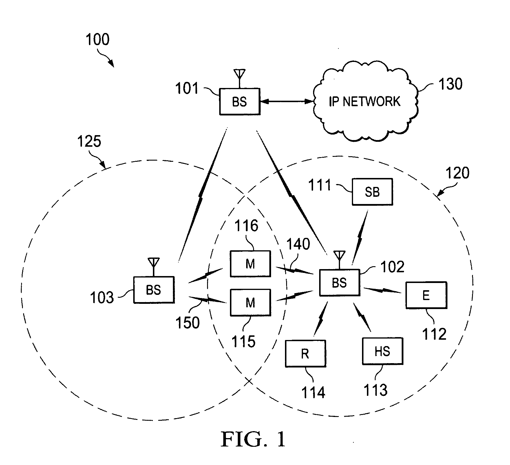
[0027]FIG. 1 illustrates ex...


PUM


Abstract

A relay station in a wireless communication system is configured to relay communications between the base station and a plurality of subscriber stations. The relay station includes at least one antenna configured to transmit and receive data and control information. The relay station also includes a controller coupled to the antenna. The controller is configured to transmit control information to a subscriber station during a first set of symbols in a relay station to subscriber station (RS-to-SS) subframe. The controller also switches the antenna to a receive mode; and receives control information during a second set of symbols in the RS-to-SS subframe.

Description

CROSS-REFERENCE TO RELATED APPLICATION(S) AND CLAIM OF PRIORITY[0001]The present application is related to U.S. Provisional Patent Application No. 61 / 212,027, filed Apr. 6, 2009, entitled “CONTROL AND DATA CHANNELS FOR ADVANCED RELAY OPERATION”. Provisional Patent Application No. 61 / 212,027 is assigned to the assignee of the present application and is hereby incorporated by reference into the present application as if fully set forth herein. The present application hereby claims priority under 35 U.S.C. §119(e) to U.S. Provisional Patent Application No. 61 / 212,027.TECHNICAL FIELD OF THE INVENTION[0002]The present application relates generally to wireless communications and, more specifically, to a control and data channels for relay nodes in a wireless communication system.BACKGROUND OF THE INVENTION[0003]Relay stations (hereinafter “RS”) are added to wireless communication networks to increase the coverage range, user data rates, or both, at the periphery of the cellular coverage a...

Claims


Application Information

Patent Timeline
Patent Type & Authority Applications(United States)
IPC IPC(8): H04B3/36H04L1/18G06F11/14
CPCH04B7/15507H04B7/2606H04W88/04H04W28/06H04W16/26
Inventor WANG, YANZHANG, JIANZHONGCHO, JOONYOUNGHAN, JIN-KYU
Owner SAMSUNG ELECTRONICS CO LTD
Why Eureka
Try Eureka