Rotary slide valve, in particular for a coolant circuit, which has a plurality of branches, of an internal combustion engine; electromechanical assembly

a technology of coolant circuit and rotary slide valve, which is applied in the direction of machines/engines, mechanical equipment, transportation and packaging, etc., can solve the problems of comparatively low driving force expenditure and need for low torqu

Inactive Publication Date: 2010-11-11
AUDI AG
View PDF10 Cites 68 Cited by
  • Summary
  • Abstract
  • Description
  • Claims
  • Application Information

AI Technical Summary

Benefits of technology

[0011]The object of the invention is achieved by at least one means which couples the cross section adjustment members to one another and which produces a rotational angle difference between the cross section adjustment members. The rotary slide valve according to the invention therefore has a means which couples the cross section adjustment members to one another so that, for example, the motion of onecross section adjustment member is transferred to the next cross section adjustment member, the means being made such that it produces a rotational angle difference between the cross section adjustment members. Coupling the two cross section adjustment members to the means which produces the rotational angle difference results, for example, in that one revolution of one cross section adjustment member is not transferred 1:1 to the cross section adjustment member coupled to it. This affords the advantage that the angular positions of rotation of the different cross section adjustment members are not directly dependent on one another, but individual adjustment of the cross section adjustment members and thus of the flow cross sections is possible.

Problems solved by technology

In the step-down gear one rotary element, compared to a step-up gear, must be turned farther and more quickly, however, lower torque is necessary so that the expenditure of force for driving is comparatively low.

Method used


Image

  • Rotary slide valve, in particular for a coolant circuit, which has a plurality of branches, of an internal combustion engine; electromechanical assembly
  • Rotary slide valve, in particular for a coolant circuit, which has a plurality of branches, of an internal combustion engine; electromechanical assembly
  • Rotary slide valve, in particular for a coolant circuit, which has a plurality of branches, of an internal combustion engine; electromechanical assembly

Examples


Embodiment Construction

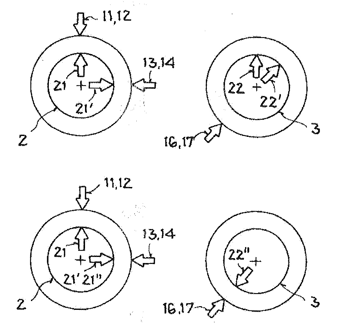
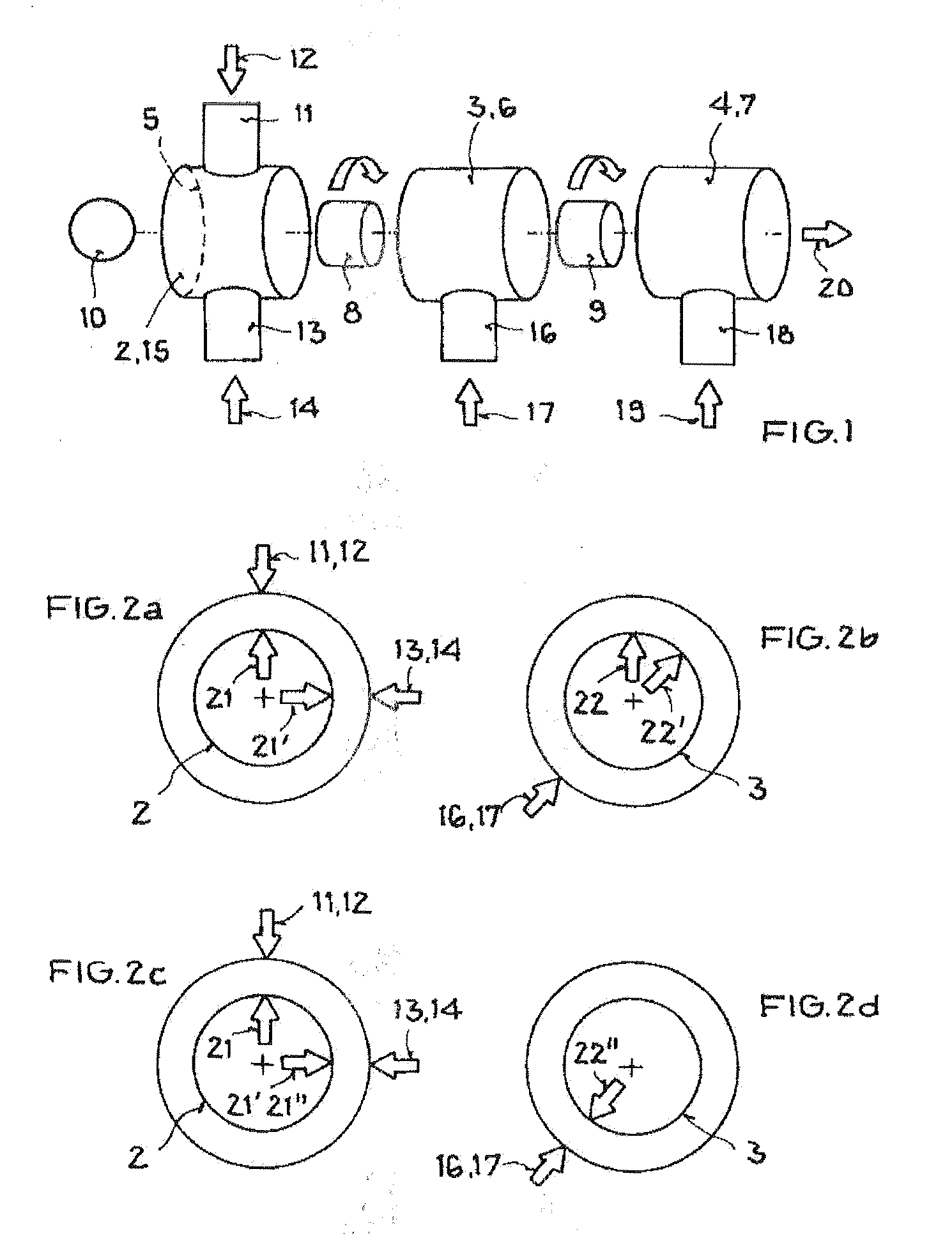
[0066]FIG. 1 shows in a schematic one exemplary embodiment of a three-stage rotary slide valve 1 according to the invention with three cross section adjustment members 2, 3, and 4 which are made respectively in one piece with one of the rotary elements 5, 6, and 7. Each of the two cross section adjustment members 2, 3 and 3, 4 are dynamically connected to one another by way of the rotary driving gear in the form of step-down gears 8 and 9. The first cross section adjustment member 2 is driven by a motor actuator 10. The cross section adjustment member 2 interacts with the feed 11 of the large coolant circuit 12 and with the feed 13 of the small coolant circuit 14, the cross section adjustment member 2 having an opening which is not shown here and which, depending on the rotary position of the cross section adjustment member 2 or of the rotary element 5, corresponds with one of the feeds 11 or 13, so that a flow cross section for one of the two coolant circuits 12, 14 can be cleared ...


PUM


Abstract

A valve assembly for the coolant system of an internal combustion engine including a housing, at least two coaxially disposed rotary valves journaled in such housing, each of such valves having an axially disposed fluid passageway communicable with an inlet port of such housing and at least one passageway communicating with the axially disposed passageway and communicable with an outlet port of the housing upon a particular orientation of such valve, and a drive gear operatively connected to such valves, operative to rotate such valves to different degrees.

Description

[0001]The invention relates to a rotary slide valve for the coolant circuit of an internal combustion engine, which circuit has a plurality of branches with a plurality of cross section adjustment members.[0002]Furthermore, the invention relates to a rotary slide valve with at least one pivoted cross section adjustment member and a base member which adjoins the cross section adjustment member with the interposition of at least one seal.[0003]Furthermore, the invention relates to a rotary slide valve with at least one cross sectional adjustment member which is pivoted in a base member.[0004]Finally, the invention relates to an electromechanical assembly.BACKGROUND OF THE INVENTION[0005]The prior art discloses rotary slide valves which, using a plurality of cross section adjustment members, set different flow cross sections for different flow rates, the cross section adjustment members either being connected tightly to one another so that they each execute the same rotary motion and t...

Claims


Application Information

Patent Timeline
Patent Type & Authority Applications(United States)
IPC IPC(8): F01P7/14
CPCF16K11/10F16K11/0856Y10T137/86831Y10T137/86549Y10T137/86871
Inventor STOERMER, MARKUS
Owner AUDI AG
Why Eureka
Try Eureka