

All Optical 1+1 Protection Unit Using Sub-Carrier Modulation Protocol
a protection unit and sub-carrier technology, applied in the field of optical networks, can solve problems such as the consumption of valuable resources by arrangemen
- Summary
- Abstract
- Description
- Claims
- Application Information
AI Technical Summary
Problems solved by technology
Method used
Image

Examples
Embodiment Construction
Overview
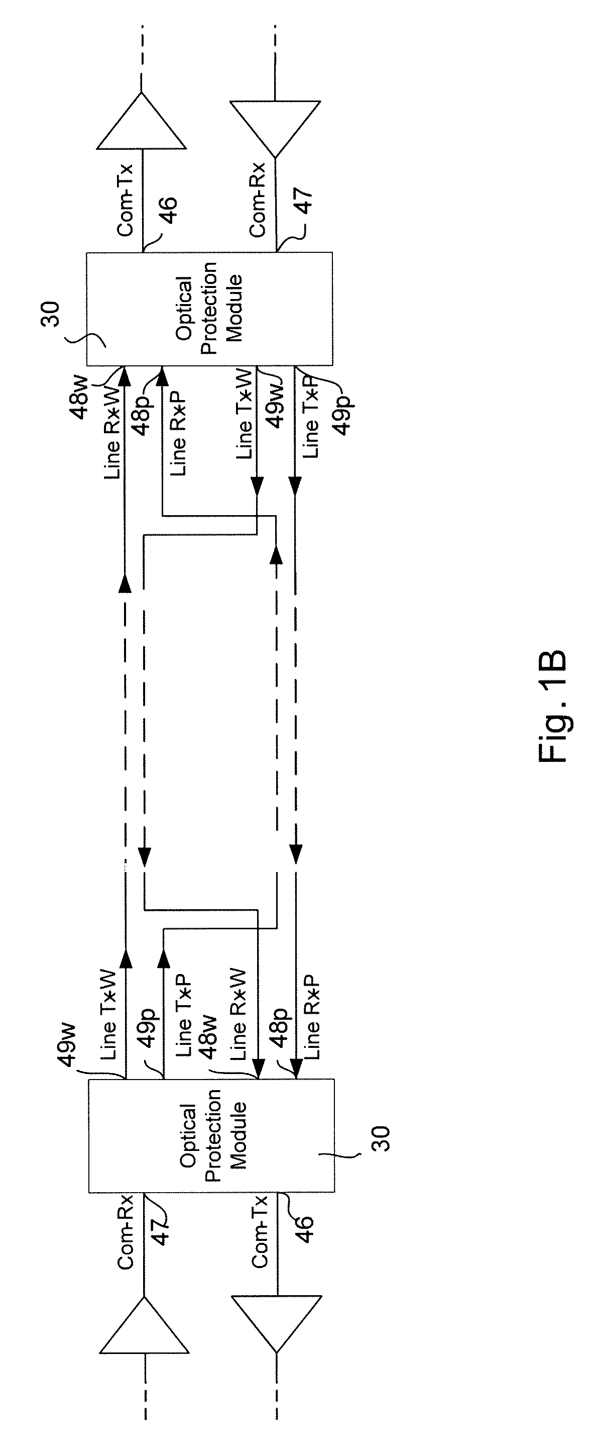
[0010]One aspect provides for an interface between a network component and an optical fiber section to a remote interface and a remote network component at an opposite end of the optical fiber section with the optical fiber section having transmitting optical fibers and receiving optical fibers. The interface comprises: a network component input port which receives optical signals from the network component; a network component output port which transmits optical signals to the network component; an optical fiber link output port which sends optical signals from the network component input port to the optical fiber section and the remote interface and component; an optical fiber link input port which receives optical signals from the optical fiber link for the network component output port; a switch unit which selects which receiving optical fibers of the optical fiber link for optical signals for the network component output port; a plurality of photodiode which monitor opt...
PUM
 Abstract
Description
Claims
Application Information