Optical fiber acceleration transducer probe and acceleration transducer system
An acceleration sensor and optical fiber sensor head technology, applied in the field of inertial sensors, can solve the problems of small dynamic range, weak anti-electromagnetic interference ability, low sensitivity and resolution, etc.
- Summary
- Abstract
- Description
- Claims
- Application Information
AI Technical Summary
Problems solved by technology
Method used
Image
Examples
Embodiment 1
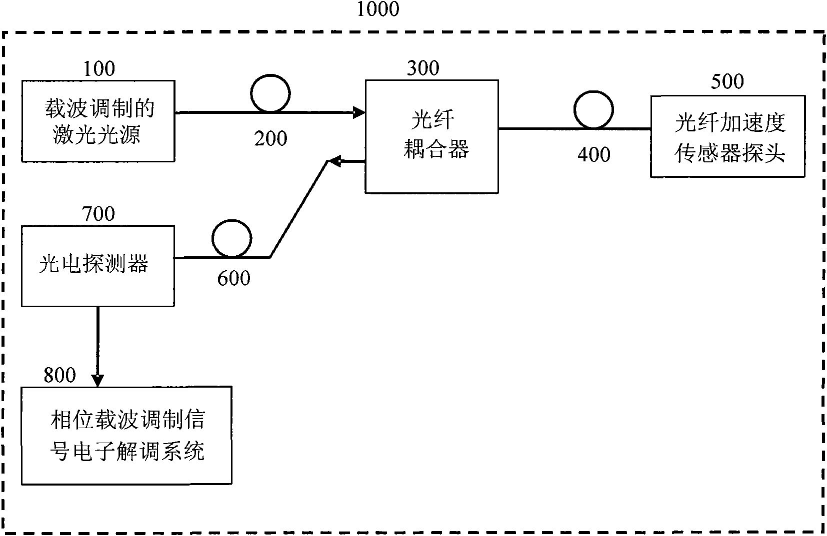
[0081] figure 1 It is a schematic block diagram of an embodiment of the optical fiber acceleration sensor system based on phase carrier modulation of the present invention. Such as figure 1 As shown, a fiber optic acceleration sensor system 1000 based on phase carrier modulation of the present invention includes: a laser light source 100 of phase carrier modulation, an input fiber 200, a fiber coupler 300, a transmission fiber 400, a fiber optic acceleration sensor probe 500, and an output fiber 600, a photodetector 700 and an electronic demodulation system 800 for carrier modulation signals. The fiber coupler 300 is connected with the phase carrier modulated laser light source 100, the fiber acceleration sensor probe 500 and the photodetector 700 respectively through the input fiber 200 and the transmission fiber 400 And the output optical fiber 600 is connected. The photodetector 700 is connected with the phase carrier modulation signal electronic demodulation system 800 ...
Embodiment 2
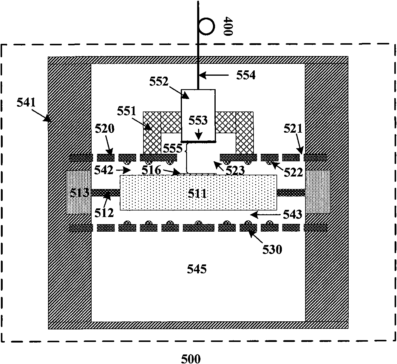
[0090] figure 2 It is a schematic diagram of the structure of the fiber optic acceleration sensor probe in an embodiment of the phase carrier modulation based fiber optic acceleration sensor system of the present invention, especially the detailed structure of the fiber optic acceleration sensor probe 500 is given.
[0091] Such as figure 2 As shown, in this embodiment, the fiber optic acceleration sensor probe 500 includes an acceleration detection structure 510 , back plates 520 and 530 , an acceleration sensor frame 541 , and a fiber optic sensor head 550 .
[0092] The acceleration detection structure 510 includes a detection mass 511 , an elastic vibrating membrane 512 , a support member 513 and a reflective film area 516 on the surface of the detection mass. Wherein the proof mass 511 is located at the center of the acceleration sensor probe 500, its boundary is connected to the inner boundary of the elastic vibrating membrane 512, and the outer boundary of the elasti...
Embodiment 3
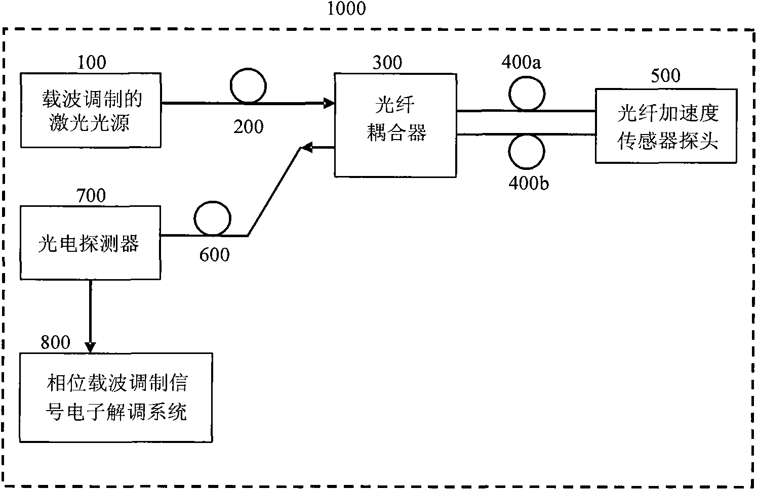
[0102] image 3 It is a schematic block diagram of an embodiment of the differential optical fiber acceleration sensor system based on phase carrier modulation of the present invention. Such as image 3 As shown, a fiber optic acceleration sensor system 1000 based on phase carrier modulation of the present invention includes: a laser light source 100 modulated by phase carrier, an input fiber 200, a fiber coupler 300, transmission fibers 400a, 400b, a fiber optic acceleration sensor probe 500, Output optical fiber 600, photodetector 700, phase carrier modulation signal electronic demodulation system 800.
[0103] The fiber coupler 300 is connected to the phase carrier modulated laser light source 100 through the input fiber 200, connected to the fiber optic acceleration sensor probe 500 through the transmission fibers 400a, 400b, and connected to the optical fiber acceleration sensor probe 500 through the The output optical fiber 600 described above is connected to the photo...
PUM
 Abstract
Description
Claims
Application Information
 - R&D
- Intellectual Property
- Life Sciences
- Materials
- Tech Scout
- Unparalleled Data Quality
- Higher Quality Content
- 60% Fewer Hallucinations
Browse by: Latest US Patents, China's latest patents, Technical Efficacy Thesaurus, Application Domain, Technology Topic, Popular Technical Reports.
© 2025 PatSnap. All rights reserved.Legal|Privacy policy|Modern Slavery Act Transparency Statement|Sitemap|About US| Contact US: help@patsnap.com


