Visible ray communication system, transmission apparatus, and signal transmission method

a transmission apparatus and visible ray technology, applied in the field of visible ray communication system, transmission apparatus, and signal transmission method, can solve the problems of increased peak to average power ratio (papr) and unsuitable handling of such a wide dynamic range signal, so as to improve frequency use efficiency and endurance, improve communication performance, and reduce manufacturing cost of transmission apparatus

Active Publication Date: 2011-09-22
SAMSUNG ELECTRONICS CO LTD
View PDF9 Cites 39 Cited by
  • Summary
  • Abstract
  • Description
  • Claims
  • Application Information

AI Technical Summary

Benefits of technology

[0010]Accordingly, the present invention has been made to solve the above-mentioned problems occurring in the prior art, and the present invention provides a visible ray communication system, a transmission apparatus, and a signal transmission method, in which the performance requirement for a high dynamic range is not imposed on a light-emitting device, the improvement of communication quality, similar to that achieved by OFDM, can be achieved, and more data can be transmitted with a predetermined number of multiplexing processes.

Problems solved by technology

However, in OFDM, there is a problem in that a Peak to Average Power Ratio (PAPR) is increased.
However, in general, an LED is used for emitting light with a predetermined quantity, and, thus, is actually not appropriate for handling such a wide dynamic range signal because it requires a special element.

Method used


Image

  • Visible ray communication system, transmission apparatus, and signal transmission method
  • Visible ray communication system, transmission apparatus, and signal transmission method
  • Visible ray communication system, transmission apparatus, and signal transmission method

Examples


embodiment

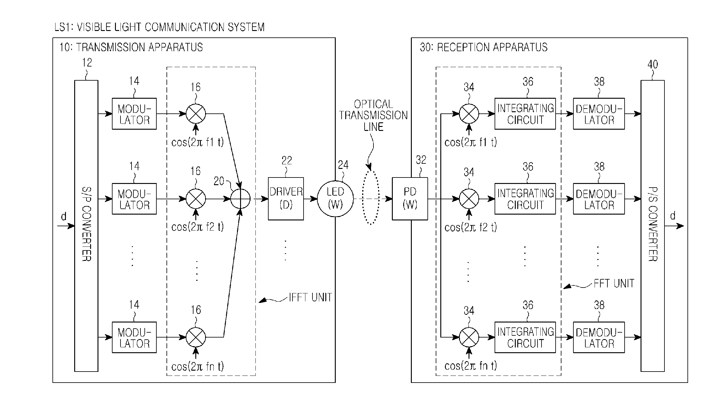
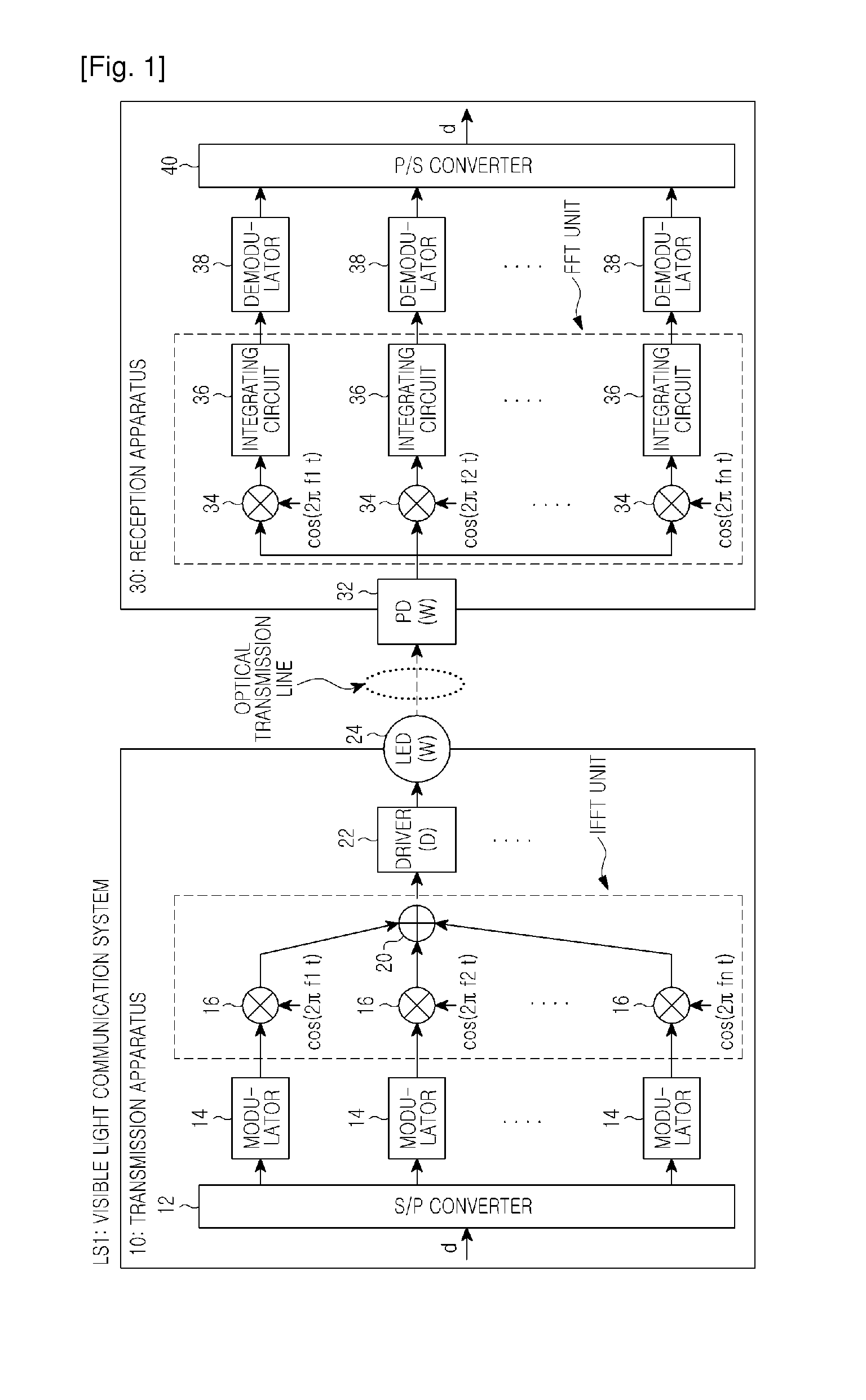
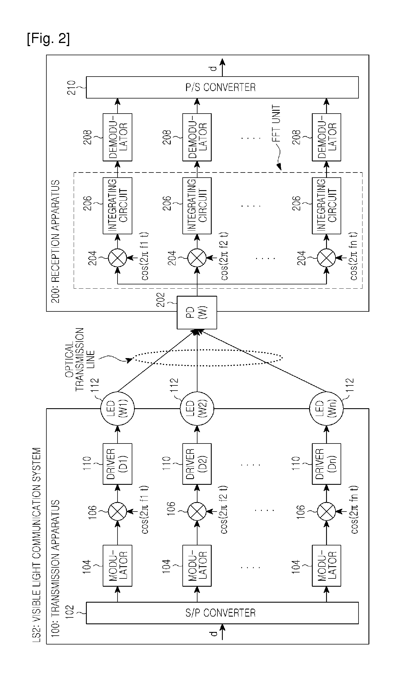
[0039]Hereinafter, one embodiment of the present invention will be described. In the present embodiment, IFFT is not performed at a transmission-side, and for each carrier, a light-emitting device is directly driven. This is for reducing the performance requirements imposed on a driver circuit and a light-emitting device.

Configuration of a Visible Ray Communication System LS2

[0040]First, the configuration of a visible ray communication system LS2 related to the present embodiment will be described with reference to FIG. 2. FIG. 2 illustrates an example of the configuration of a visible ray communication system LS2 according to the present embodiment.

[0041]As shown in FIG. 2, the visible ray communication system LS2 includes a transmission apparatus 100, and a reception apparatus 200. The transmission apparatus 100 has an S / P converter 102, a modulator 104, a multiplier 106, a driver circuit 110, and a light-emitting device 112. The reception apparatus 200 has a light-receiving devic...


PUM


Abstract

Disclosed is a visible ray communication system including a transmission apparatus and a reception apparatus, wherein the transmission apparatus includes: a plurality of light emitting devices; an S / P converter for serial-to-parallel converting transmission data, thereby generating N data streams; a modulator for modulating the generated N data streams for respective carriers with a predetermined number of dimensions, thereby generating N modulated signals; a carrier signal multiplier for multiplying the generated N modulated signals by orthogonal N carrier signals, respectively, thereby generating N transmission signals; and a light emitting control unit for illuminating the plurality of light emitting devices according to the generated N transmission signals.

Description

PRIORITY[0001]This application claims priority under 35 U.S.C. §365(c) to International Application No. PCT / KR2009 / 006923 filed in the Korean Intellectual Property Office (RO / KR) on Nov. 24, 2009, and priority under 35 U.S.C. §119(a) to Patent Application No. 2008-298941 filed in the Japanese Patent Office on Nov. 25, 2008, the entire disclosures of which are incorporated herein by reference.BACKGROUND OF THE INVENTION[0002]1. Field of the Invention[0003]The present invention relates generally to a visible ray communication system, a transmission apparatus, and a signal transmission method.[0004]2. Description of the Related Art[0005]An optical communication technology using light in a visible ray region has recently been explored. In particular, as an illuminating device using a luminous element, such as an Light-emitting Diode (LED) Light-emitting, has rapidly come into use, development of technology for achieving higher speed, convenient data communication by utilizing an infrast...

Claims


Application Information

Patent Timeline
Patent Type & Authority Applications(United States)
IPC IPC(8): H04J14/00H04B10/11H04B10/116H04B10/54H04J14/02
CPCH04B10/116H04B10/50H04L27/26H04B10/11H04B10/112H04B10/114
Inventor YOKOI, ATSUYA
Owner SAMSUNG ELECTRONICS CO LTD
Why Eureka
Try Eureka