Methods and systems for simulating beam-to-surface contacts in finite element analysis

a finite element analysis and beam-to-surface technology, applied in the field of computer-aided engineering analysis, can solve the problems of insufficient and inefficient prior art approaches to simulate such contacts

Active Publication Date: 2010-11-11
ANSYS
View PDF30 Cites 8 Cited by
  • Summary
  • Abstract
  • Description
  • Claims
  • Application Information

AI Technical Summary

Benefits of technology

[0007]This section is for the purpose of summarizing some aspects of the present invention and to briefly introduce some preferred embodiments. Simplifications or omissions in this section as wel

Problems solved by technology

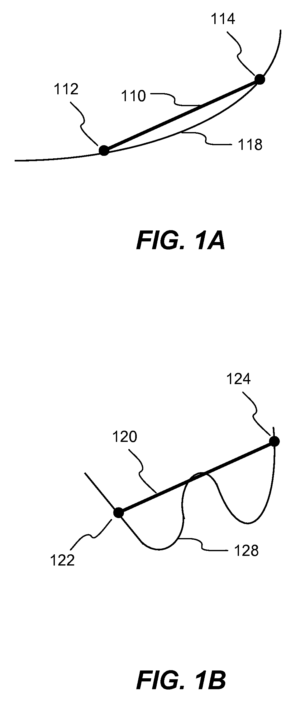
One of the most challenging simulations is related to contacts between two or more locations of the FEA model.
Prior art approaches to simulate such contacts have been inadequate and inefficient, particularly when the surface mesh contains

Method used


Image

  • Methods and systems for simulating beam-to-surface contacts in finite element analysis
  • Methods and systems for simulating beam-to-surface contacts in finite element analysis
  • Methods and systems for simulating beam-to-surface contacts in finite element analysis

Examples


Embodiment Construction

[0019]In the following description, numerous specific details are set forth in order to provide a thorough understanding of the present invention. However, it will become obvious to those skilled in the art that the present invention may be practiced without these specific details. The descriptions and representations herein are the common means used by those experienced or skilled in the art to most effectively convey the substance of their work to others skilled in the art. In other instances, well-known methods, procedures, and components have not been described in detail to avoid unnecessarily obscuring aspects of the present invention.

[0020]Reference herein to “one embodiment” or “an embodiment” means that a particular feature, structure, or characteristic described in connection with the embodiment can be included in at least one embodiment of the invention. The appearances of the phrase “in one embodiment” in various places in the specification are not necessarily all referri...


PUM


Abstract

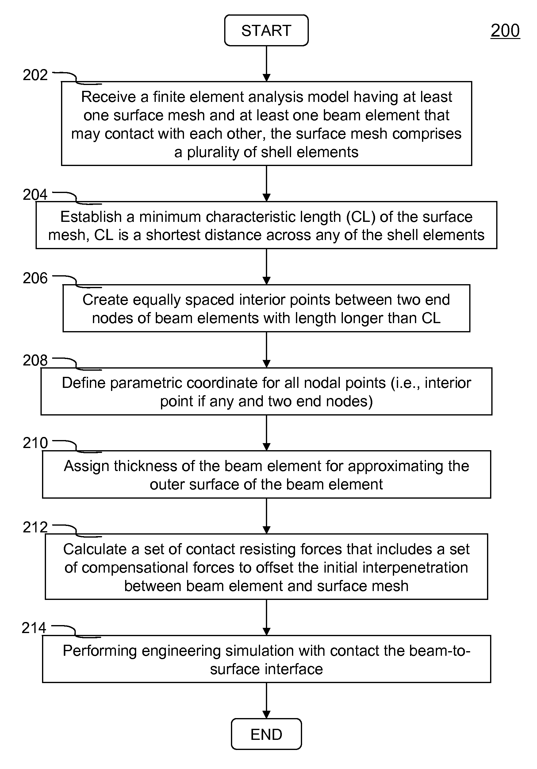
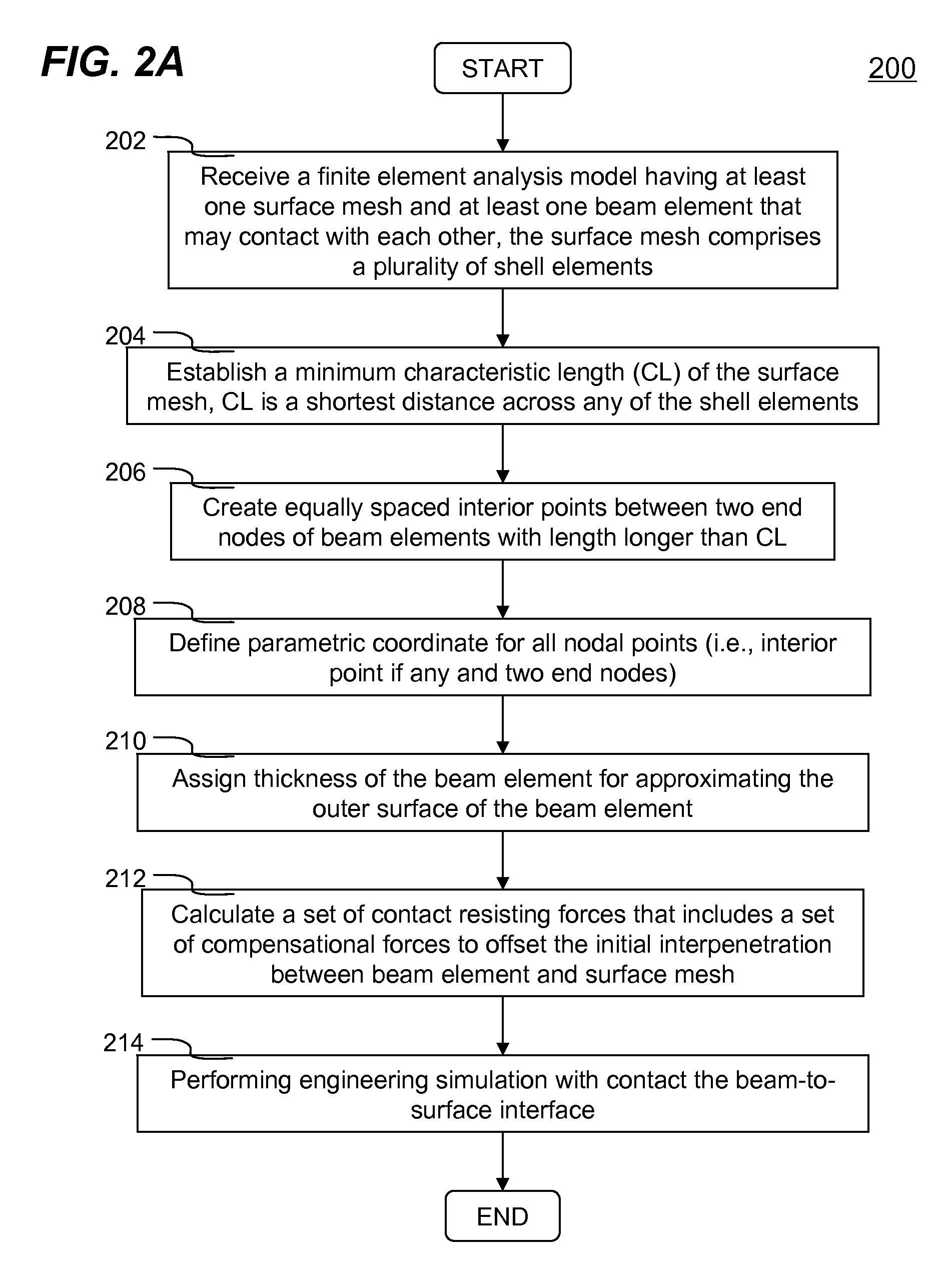
Methods and systems for simulating beam-to-surface contacts in finite element analysis (FEA) are disclosed. A FEA model contains at least one beam element and at least one surface mesh. Surface mesh comprises a plurality of two-dimensional finite elements having arbitrary mesh density. A minimum characteristic length (CL) of the surface mesh is calculated. One or more interior points are defined for those beam elements with length longer than CL. For every nodal point (i.e., end nodes and interior points if any), a parametric coordinate between 0 and 1 inclusive is established and kept constant throughout the FEA analysis. Distributed nodal masses are used for calculating a stiffness value for calculating nodal force to resist penetration. Initial penetration with the surface mesh at each nodal point along the beam element is compensated with a set of displacements subtracting from the initial nodal displacements, such that the compensational forces remain at zero as the nodal point's initial interpenetration decreases.

Description

CROSS-REFERENCE TO RELATED APPLICATION[0001]This application claims priority from a co-pending U.S. Provisional Patent Application Ser. No. 61 / 175,862 filed May 6, 2009, the entire contents of which are incorporated herein by reference.FIELD OF THE INVENTION[0002]The present invention generally relates to computer aided engineering analysis, more particularly to improved methods and systems for simulating beam-to-surface contacts in finite element analysis used for a time-marching engineering simulation for assisting users to make decision in improvement of an engineering product (e.g., car, airplane) design.BACKGROUND OF THE INVENTION[0003]Computer aided engineering (CAE) has been used for supporting engineers in many tasks. For example, in a structure or product design procedure, CAE analysis, in particular finite element analysis (FEA), has often been employed to evaluate responses (e.g., stresses, displacements, etc.) under various loading conditions (e.g., static or dynamic).[0...

Claims


Application Information

Patent Timeline
IPC IPC(8): G06F17/10
CPCG06F17/5018G06F30/23
Inventor HALLQUIST, JOHN O.
Owner ANSYS
Why Eureka
Try Eureka