

North-bridge to south-bridge protocol for placing processor in low power state
- Summary
- Abstract
- Description
- Claims
- Application Information
AI Technical Summary
Benefits of technology
Problems solved by technology
Method used
Image

Examples
Embodiment Construction
)
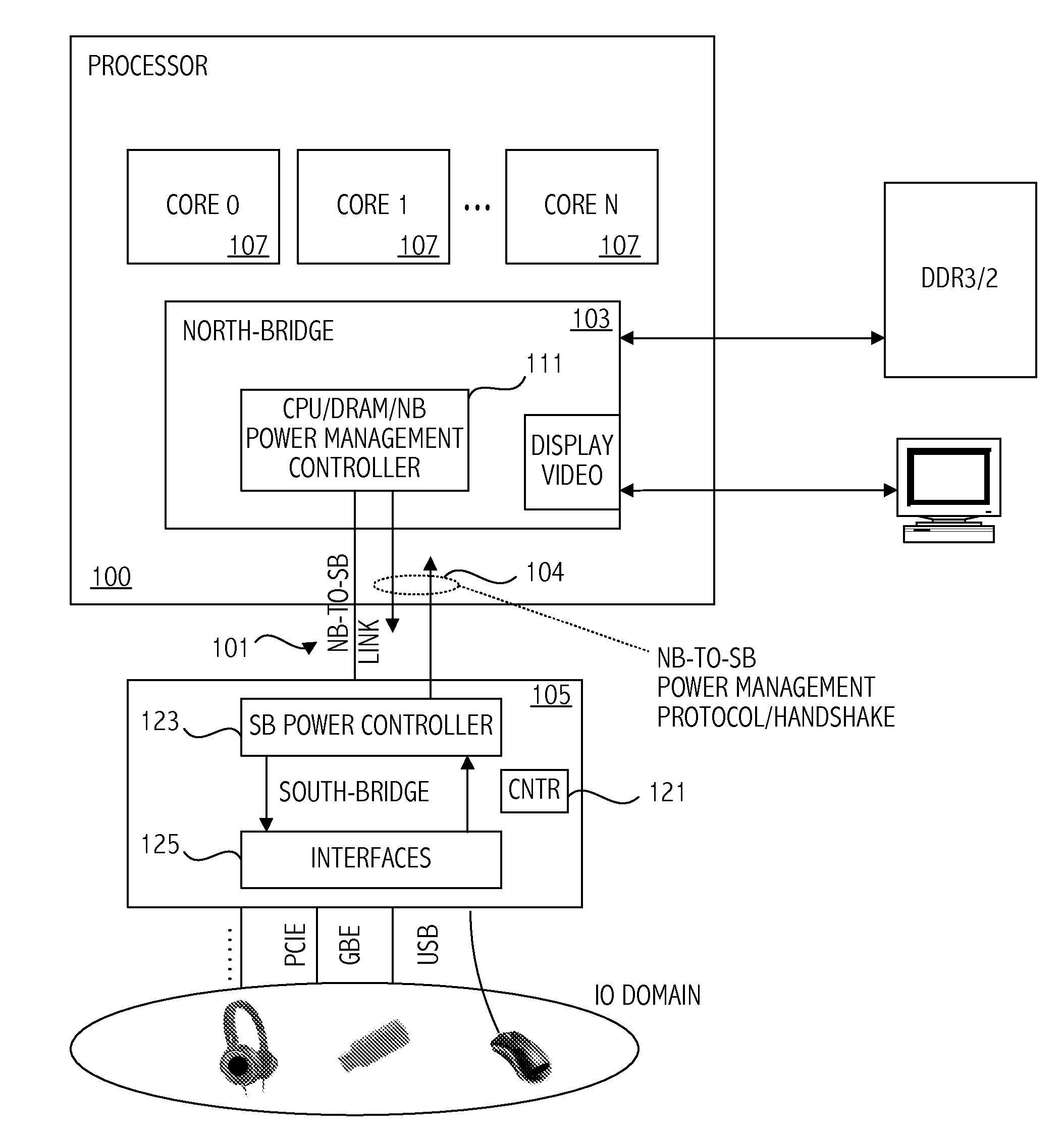
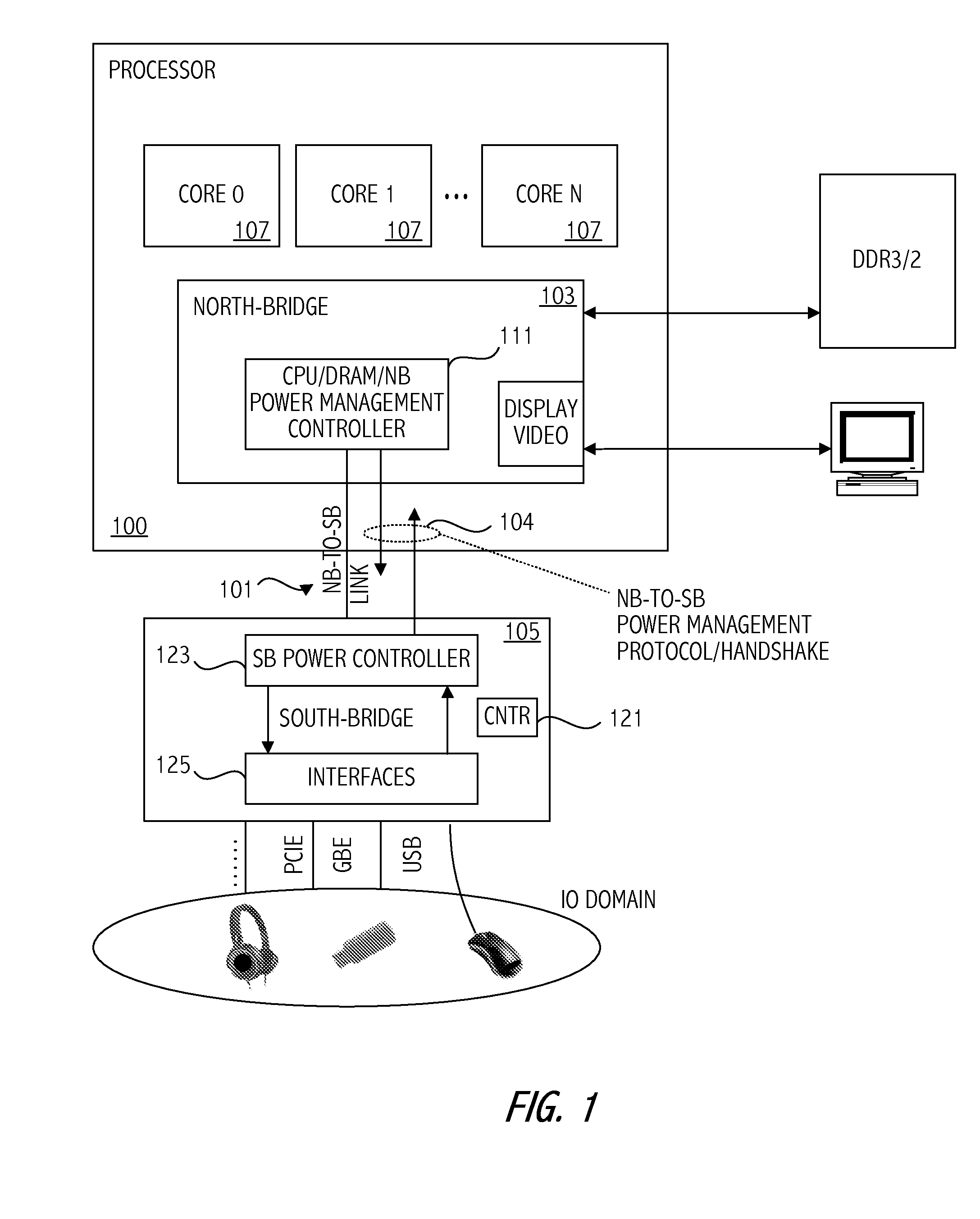
[0019]Referring to FIG. 1, a high level conceptual block diagram of a computer system according to an embodiment of the present invention is illustrated. In the illustrated embodiment, North-Bridge-to-South-Bridge power management protocol is implemented and maintained over a North-Bridge-to-South-Bridge link 101 coupling the North-Bridge (NB) 103 and the South-Bridge (SB) 105. The North-Bridge-to-South-Bridge link 101 provides a dynamic protocol between the North-Bridge and South-Bridge allowing the South-Bridge to participate in the power state transition decisions. The South-Bridge 105 (also referred to as an I / O Controller Hub) represents the input / output (I / O) domain, “presiding” over I / O devices and main I / O controllers. The North-Bridge activity monitors and activity predictors have only partial knowledge about incoming streams, and therefore the possibility of misprediction is not negligible. The South-Bridge is in a better position than the North-Bridge for making an accur...
PUM
 Abstract
Description
Claims
Application Information