Shoe

a technology for athletic shoes and soles, applied in the field of athletic shoes, can solve the problems of sudden increase in the feeling of the circumferential edge of the outer sole being caught, increased braking force, and increased sliding force, etc., to achieve the effect of increasing the rigidity of the outer side portion of the midsole, reducing the amount of sliding, and controlling the amount of sliding

Active Publication Date: 2010-11-18
YONEX CO LTD
View PDF15 Cites 50 Cited by
  • Summary
  • Abstract
  • Description
  • Claims
  • Application Information

AI Technical Summary

Benefits of technology

[0016]According to an athletic shoe of the present invention, since the protruding surface of the bulged portion has an extending portion formed extending in a large arcuate curve from the perimeter edge of the outersole and provided to go therearound, even when the foot makes a strong effort to hold on when sliding laterally in the side direction or the like, the force by the foot making effort to hold on acts in a concentrated manner on the portion along the little toe where the protruding bulge is formed, so that it will be difficult for the outer sole to get caught and thus a braking force would not increase suddenly. Herewith, the player need not worry about the outer sole getting caught as mentioned above, so that he / she can make effort with his / her foot to hold on with an intended strength. As a result, light footwork that matches the player's own image will be allowed, such as, the player being able to control the amount of sliding easily. Furthermore, since the rigidity of the outer side portion of the midsole is increased by the bulged portion, bearing strength acting against lateral force at sliding is increased to control the deformation in the portion, so that a stable retaining of the foot portion is obtained.
[0017]Moreover, because a large arcuate curved portion is formed to the bulged portion formed to protrude in the outward direction, the ground contact width will not be reduced compared to the conventional ones. For such reason, when sliding sideways, sufficient amount of ground contact area is ensured so that such as twisting of the ankle can be certainly avoided.

Problems solved by technology

However, with an athletic shoe with a conventional sole structure as shown in FIGS. 9-12 mentioned above, when stepping in the side direction with a strong effort to hold on to control the amount of sliding, there is a tendency for a sudden increase in the feeling that the corner of the circumferential edge of the outer sole gets caught and the braking force suddenly increases as well.
And when such a feeling of the outer sole getting caught and a sudden increase in the braking force arises, the player's ankle is twisted or the like in the outward direction, making him / her likely to lose balance.
For such reasons, the player being anxious about this will not be able to make a strong effort with his / her foot to hold on.
This results in not being able to obtain appropriate sliding that is desired or the like, leading to a problem of light footwork being impaired.
In other words, it is considered that there is a tendency that the above described problem cannot be avoided.
Additionally, the stabilizer made to protrude downward in addition to being made to protrude outward, increases the catching of the ground surface at the tip due to it being protruded in the downward direction, so again, it is considered that there is a tendency that the above described problem cannot be avoided.

Method used


Image

  • Shoe
  • Shoe
  • Shoe

Examples


first embodiment

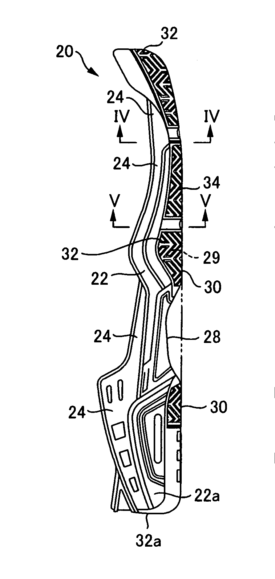
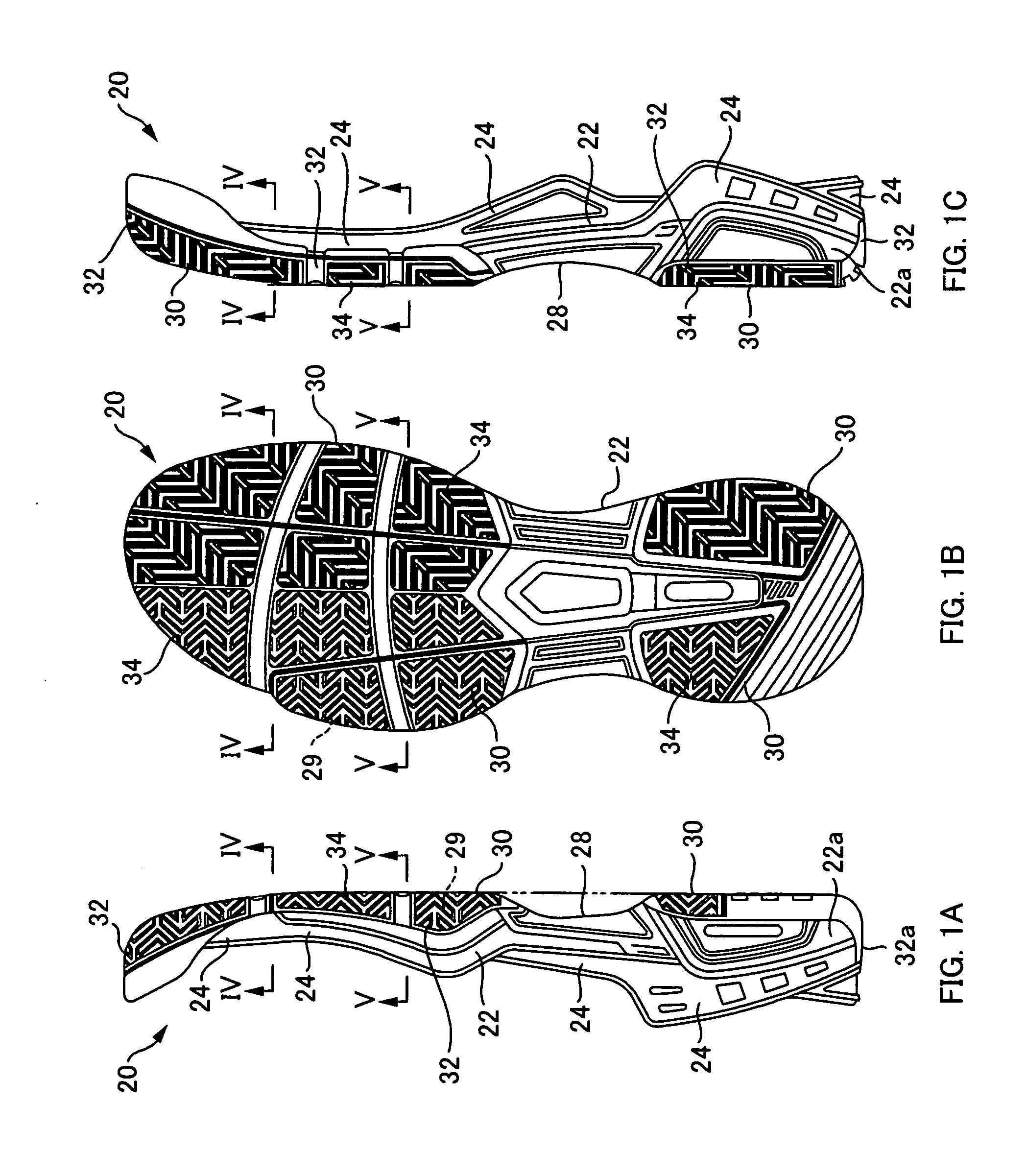
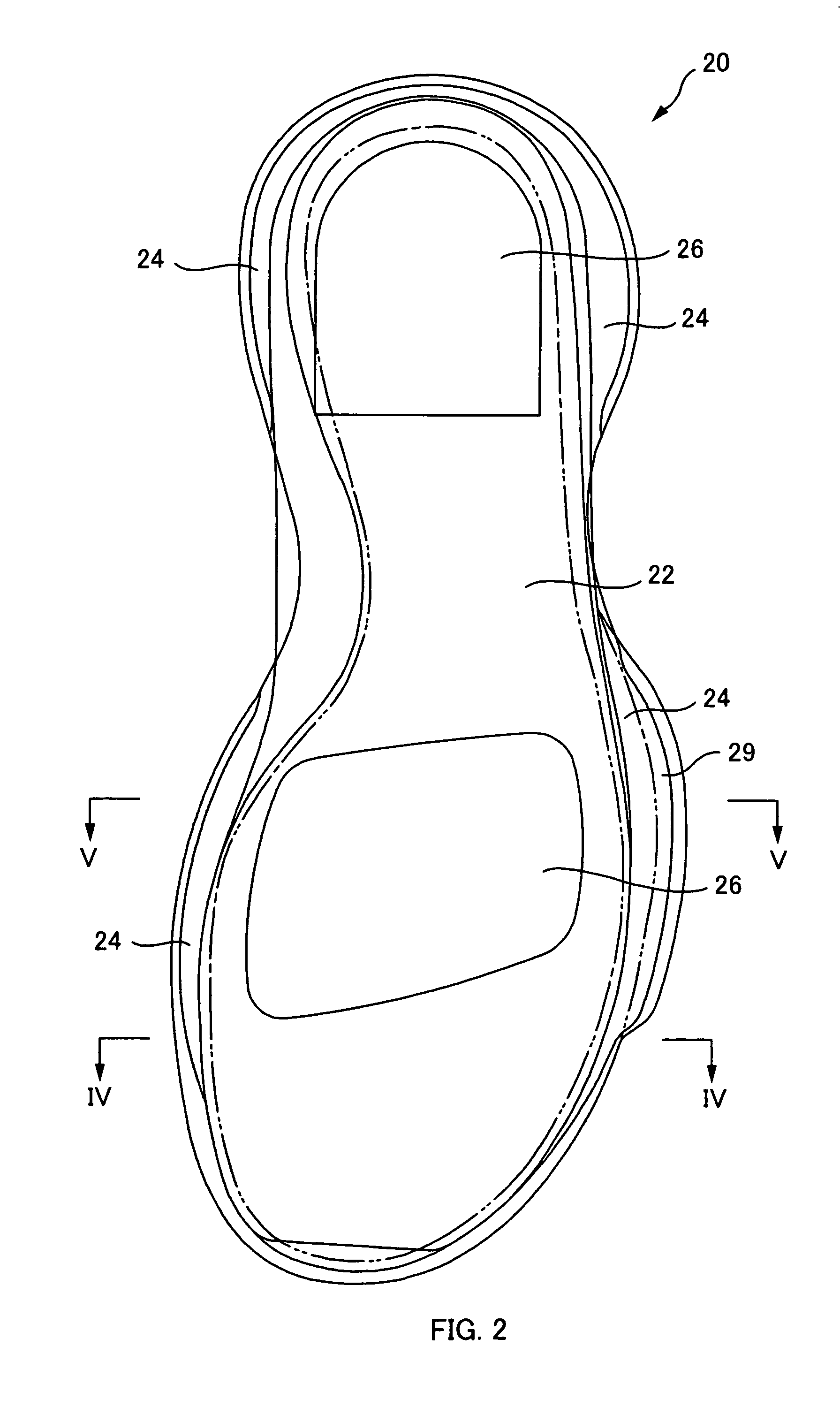
[0033]FIGS. 1-5 show a first embodiment of an athletic shoe according to the present invention, where FIG. 1(a) is a side view showing the inner side portion of a sole, FIG. 1(b) is a bottom view, FIG. 1(c) is a side view showing the outer side portion, FIG. 2 is a plan view of the sole, FIG. 3 is a view of the sole seen from the toe side, FIG. 4 is a sectional view taken along line IV-IV shown in each of the drawings in FIG. 1, and similarly FIG. 5 is a sectional view taken along line V-V shown in each of the drawings in FIG. 1.

[0034]Here, the first embodiment of the tennis shoe shown in FIGS. 1-5 is for an advanced player, and is an improved model of a conventional one explained with the drawings shown in FIGS. 9-12. Therefore, as apparent from the drawings, their configuration has a number of parts that are in common and their basic configuration is substantially the same.

[0035]To be specific, as shown in each of the drawings in FIGS. 1-5, the sole 20 of this tennis shoe has a mi...

second embodiment

[0046]FIGS. 6-8 show a second embodiment of an athletic shoe according to the present invention, where FIG. 6 is a side view of an athletic shoe, FIG. 7 is a side view showing the outer side-portion of the sole of the athletic shoe shown in FIG. 6, FIG. 8(a) is a sectional view taken along line IIXa-IIXa shown in FIG. 7, similarly, FIG. 8(b) is a sectional view taken along line IIXb-IIXb shown in FIG. 7, and FIG. 8(c) is also a sectional view taken along line IIXc-IIXc shown in FIG. 7.

[0047]Regarding the athletic shoe of the second embodiment, a reinforcing member is further provided to the previously described tennis shoe of the first embodiment, which restrains the outward swelling deformation of the upper member, from the bulged portion 29 formed at the portion along which a little toe at the circumferential side face of the midsole 22 is located to the upper member at a portion thereabove. That is, the position where the reinforcing member is placed is the point that differs fro...


PUM


Abstract

In order to provide an athletic shoe that does not get caught even when a strong effort to hold on is made when sliding sideways, and that allows for light footwork, the present invention provides an athletic shoe that has an undersurface of a midsole 22 that is formed with a raised portion 24, along a circumferential side edge thereof affixed with an outersole 30 that forms an outsole, and an extending portion 32 that extends up to a circumferential side surface of the midsole is formed at a perimeter edge of the outersole, wherein: at a portion along a little toe of the circumferential side surface 22a of the midsole, a bulged portion 29 having a thickness equal to or more than a thickness substantially corresponding to a thickness of the raised portion 24 of the midsole in a shoe width direction is integrally fanned so as to protrude outward, and the extending portion 32 is formed extending from the perimeter edge of the outersole 30 toward a protruding surface of the bulged portion 29 and the extending portion 32 is formed in a large arcuate curve and is made to go round the protruding surface of the bulged portion.

Description

CROSS REFERENCE TO RELATED APPLICATIONS[0001]The present application claims priority from Japanese Patent Application No. 2006-34106 filed on Feb. 10, 2006 and Japanese Patent Application No. 2006-246790 filed on Sep. 12, 2006 which are incorporated herein by reference.TECHNICAL FIELD[0002]The present invention relates to an athletic shoe whose sole structure is made so that light footwork can be obtained.BACKGROUND ART[0003]In general, an athletic shoe, of course requires to be lightweight but also requires to, such as, exert a firm grip of the ground surface when stepping forward or other directions, demonstrate shock absorption characteristics when landing, and show stability when sliding sideways, in other words, high rigidity against a lateral force and ability to retain the foot portion.[0004]Hence, for the purpose of satisfying the requirements like those described above, the sole constructions of the prior art have been configured as shown in FIGS. 9-12. Note that FIG. 9(a) ...

Claims


Application Information

Patent Timeline
Patent Type & Authority Applications(United States)
IPC IPC(8): A43B5/00A43B13/14
CPCA43B5/10A43B13/12A43B13/223A43B13/145A43B13/187A43B13/141A43B23/08
Inventor HIDE, KAZUSHI
Owner YONEX CO LTD
Why Eureka
Try Eureka