Pipe insertion indicator and method of use

Inactive Publication Date: 2010-11-18
SHUMARD DENNIS
View PDF16 Cites 49 Cited by
  • Summary
  • Abstract
  • Description
  • Claims
  • Application Information

AI Technical Summary

Benefits of technology

[0016]This disclosure further provides for a pipe clamp stop for a bell pipe and spigot connection system comprised of two semi-circular stop members including annular s

Problems solved by technology

Over-insertion of the spigot, so that the end of the spigot wedges against the back of the bell, induces stress that can lead to premature pipe failure.
Even if care is taken to assemble a joint properly, the force used to assemble successive joints may cause over insertion in the previous joints.
To complicate matters, over insertion is typically not discovered until the entire run of pipe has been buried.
Removal and replacement of an in

Method used


Image

  • Pipe insertion indicator and method of use
  • Pipe insertion indicator and method of use
  • Pipe insertion indicator and method of use

Examples


Embodiment Construction

[0067]The present invention is described with reference to the drawings as shown. The invention may take different forms and should not be construed as limited to the embodiments described. Like numbers refer to like elements throughout.

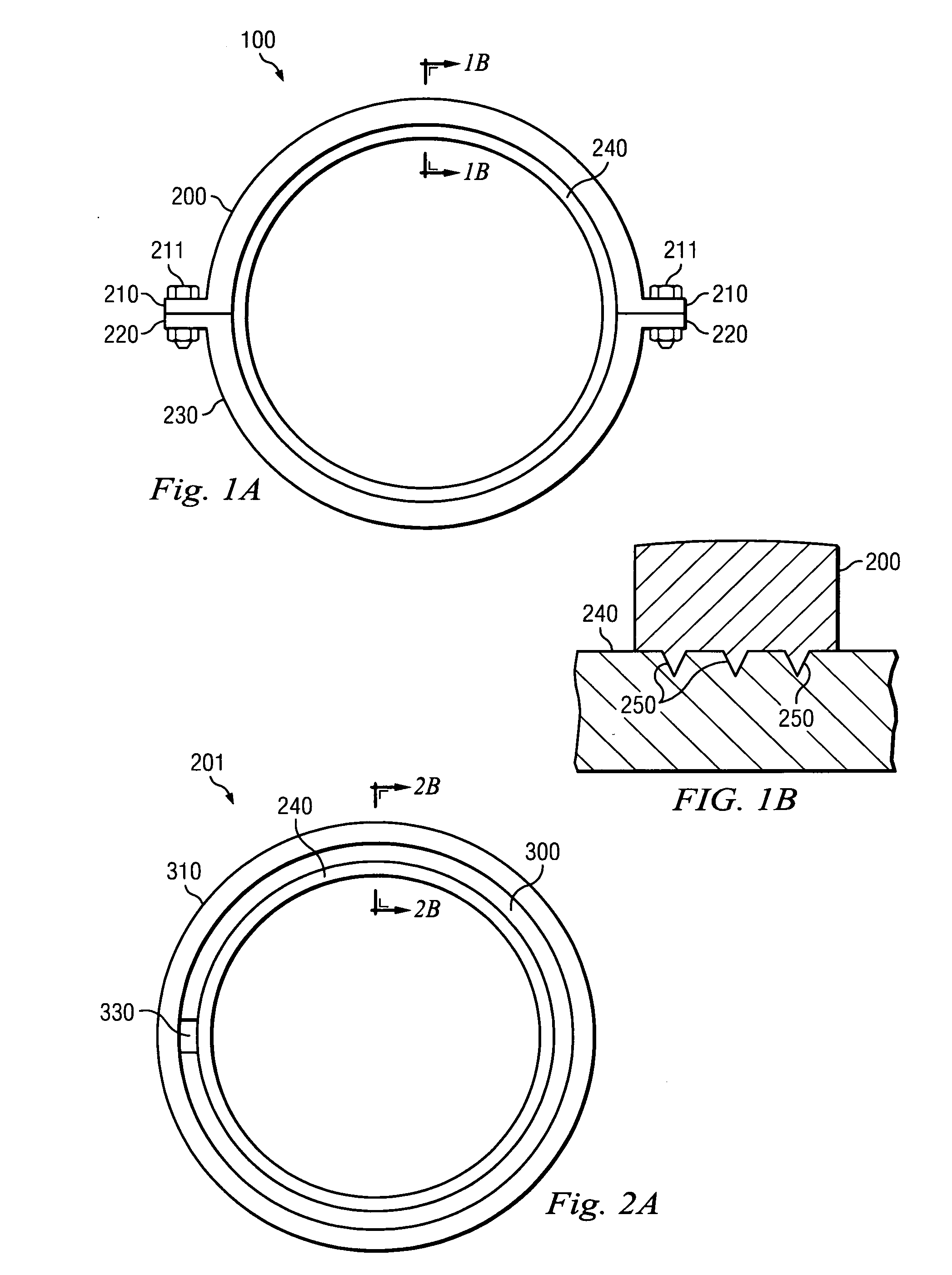
[0068]FIGS. 1A and 1B show a preferred embodiment of pipe clamp 100. Upper section 200 and lower section 230 each have flanges 210 and 220 to secure the pipe clamp around a spigot pipe 240 by use of bolts 211. As shown in FIG. 1B, the pipe clamp is includes serrations 250 that deform the outer surface of spigot pipe 240.

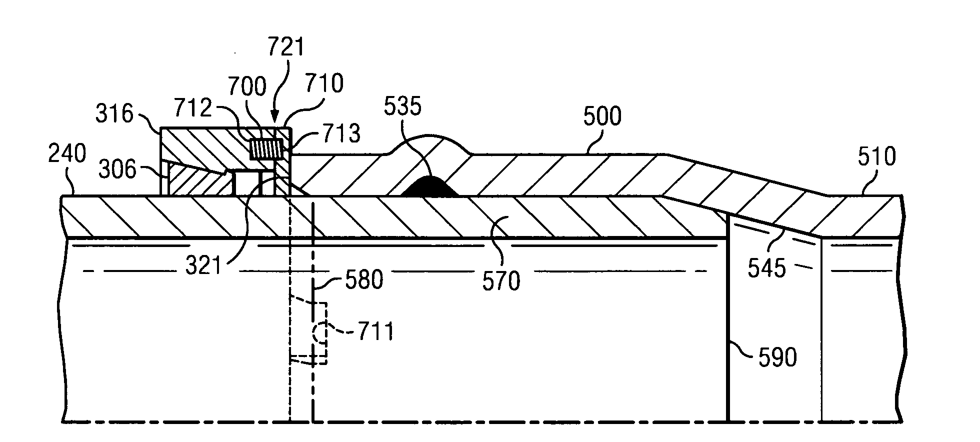
[0069]Upper section 200 and lower section 230 are positioned around a spigot and bolts 211 are placed through flanges 210 and 220 respectively. As the bolts are tightened serrations 250 embed themselves in the outer surface of spigot pipe 240. As the spigot pipe is inserted into the bell (not shown) the distance between the bell and the pipe clamp forms an indicator of an optimal insertion position. An over insertion position is preve...


PUM


Abstract

An insertion indicator is provided for a bell and spigot pipe connection system, including a stop ring positioned on the spigot pipe. An indicator is provided adjacent the stop ring and the bell pipe for indicating a proper insertion depth. A break away tab is provided as an insertion indicator which shears away upon an over insertion condition. A flexible insertion indicator tab is provided. Further, a flexible annular ring is provided to indicate insertion depth. An insertion indicator is further provided which includes an annular stop ring fixed to the spigot pipe and a bell stop ring slidingly engaging the spigot pipe, separated by resilient member. Compression deforms the resilient member which responds by moving the pipes into an optimal position. An insertion indicator is also provided which includes a first semi-circular stop member and a second semi-circular stop member which are angularly deflected creating an indication of proper insertion depth.

Description

CROSS-REFERENCE TO RELATED APPLICATIONS[0001]This application claims priority benefit from U.S. Provisional Patent Application Ser. No. 61 / 216,469 entitled “Pipe Insertion Indicator and Method of Use” filed on May 18, 2009.FIELD OF THE INVENTION[0002]This disclosure relates generally to methods of joining large underground pipes having bell and spigot joining systems.BACKGROUND[0003]In order to assemble long runs of large diameter buried pipe, multiple sections must be assembled. One system of joining pipe sections is a “bell and spigot” system. In joining the sections, the spigot of each successive pipe is inserted into the bell of the previous pipe until an optimal insertion depth is achieved. An optimal insertion position provides clearance between the end of the spigot and the back of the bell sufficient to allow joint pressurization, thermal expansion and angular joint deflection. Over-insertion of the spigot, so that the end of the spigot wedges against the back of the bell, i...

Claims


Application Information

Patent Timeline
IPC IPC(8): F16L55/00F16L35/00
CPCF16L21/03F16L2201/10F16L23/0286F16L21/08
Inventor SHUMARD, DENNIS
Owner SHUMARD DENNIS
Why Eureka
Try Eureka