Control system for controlling the electrical tilt of an antenna

a control system and antenna technology, applied in the direction of antennas, antenna details, electrical apparatus, etc., can solve the problems of high manufacturing cost, high manufacturing cost, and high manufacturing cost of the above-mentioned system, and achieve easy and inexpensive mounting, upgrading and replacement, and clean exterior appearance. , the effect of easy and inexpensive mounting

Active Publication Date: 2010-11-18
INTEL CORP
View PDF4 Cites 9 Cited by
  • Summary
  • Abstract
  • Description
  • Claims
  • Application Information

AI Technical Summary

Benefits of technology

[0010]Against this background, a primary object of the present invention is to provide an improved control system for controlling the electrical tilt of an antenna unit, such that the control system is easy to manufacture and permits easy and inexpensive mounting, upgrading and replacement. A further object is to provide an antenna system with an integrated control system which is safely contained in a casing, without any movable parts extending through the casing wall, and which has a clean exterior appearance.

Problems solved by technology

The above-mentioned systems are relatively complicated and expensive to manufacture.
However, antennas sometimes have to be replaced so as to meet new requirements and standards, and such replacement or upgrading is therefore very expensive since all parts of the system, including the antenna elements, the feed structure, the tilt adjusting mechanism and the control system, have to be replaced.
Of course, such separate units are also relatively expensive to replace at the antenna site.
Moreover, mechanical elements disposed partially outside the antenna casing are exposed to the prevailing climatic conditions and have to be sturdy and weather resistant.

Method used


Image

  • Control system for controlling the electrical tilt of an antenna
  • Control system for controlling the electrical tilt of an antenna
  • Control system for controlling the electrical tilt of an antenna

Examples


Embodiment Construction

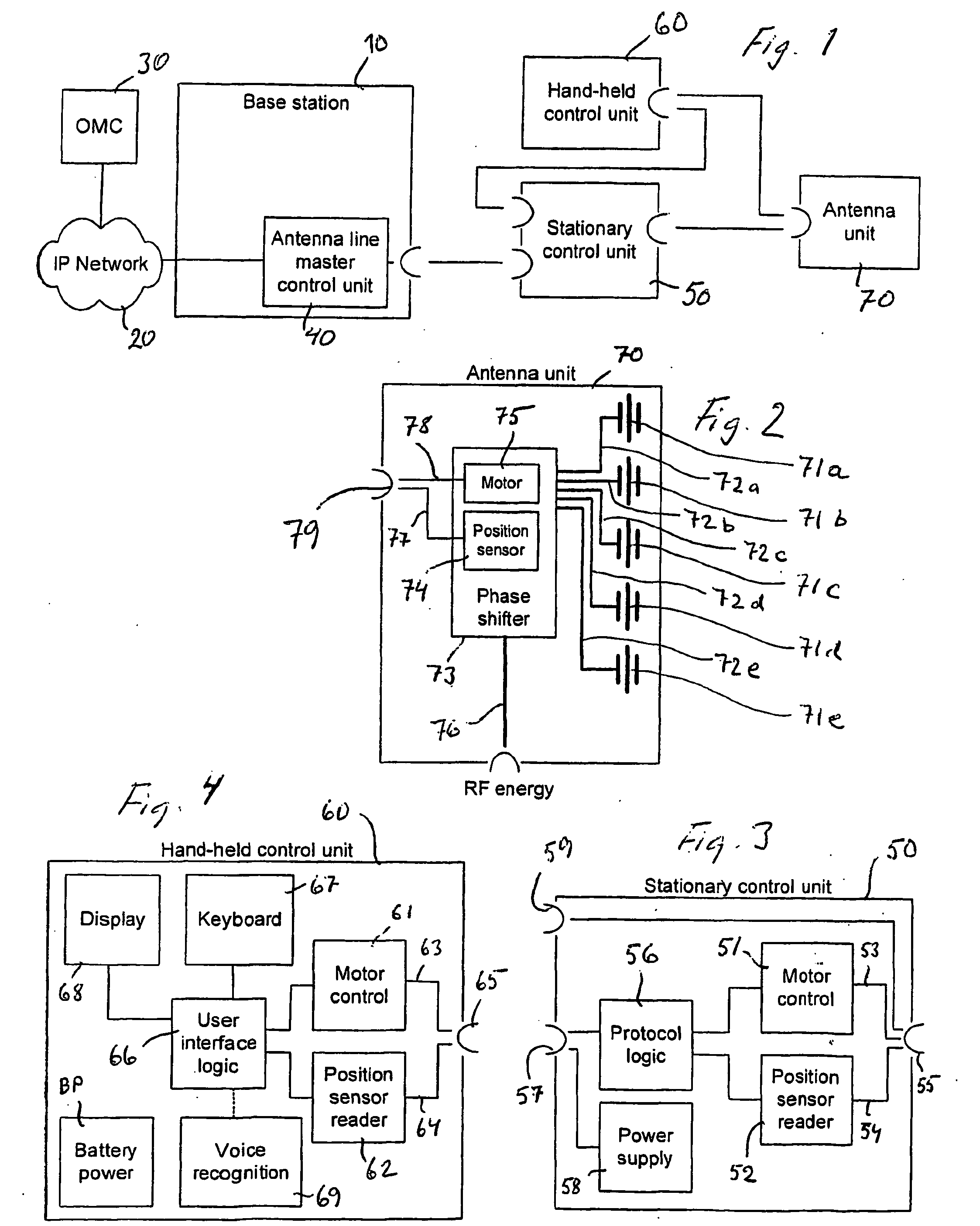
[0025]The communication system illustrated schematically in FIG. 1 includes a base station 10 being connected, on the one hand, to an IP network 20 including an operation and maintenance centre (OMC) 30, at a remote location and, on the other hand, via an antenna line master control unit (MCU) 40, an antenna system with a stationary control unit 50, a hand-held control unit 60 and an antenna unit 70.

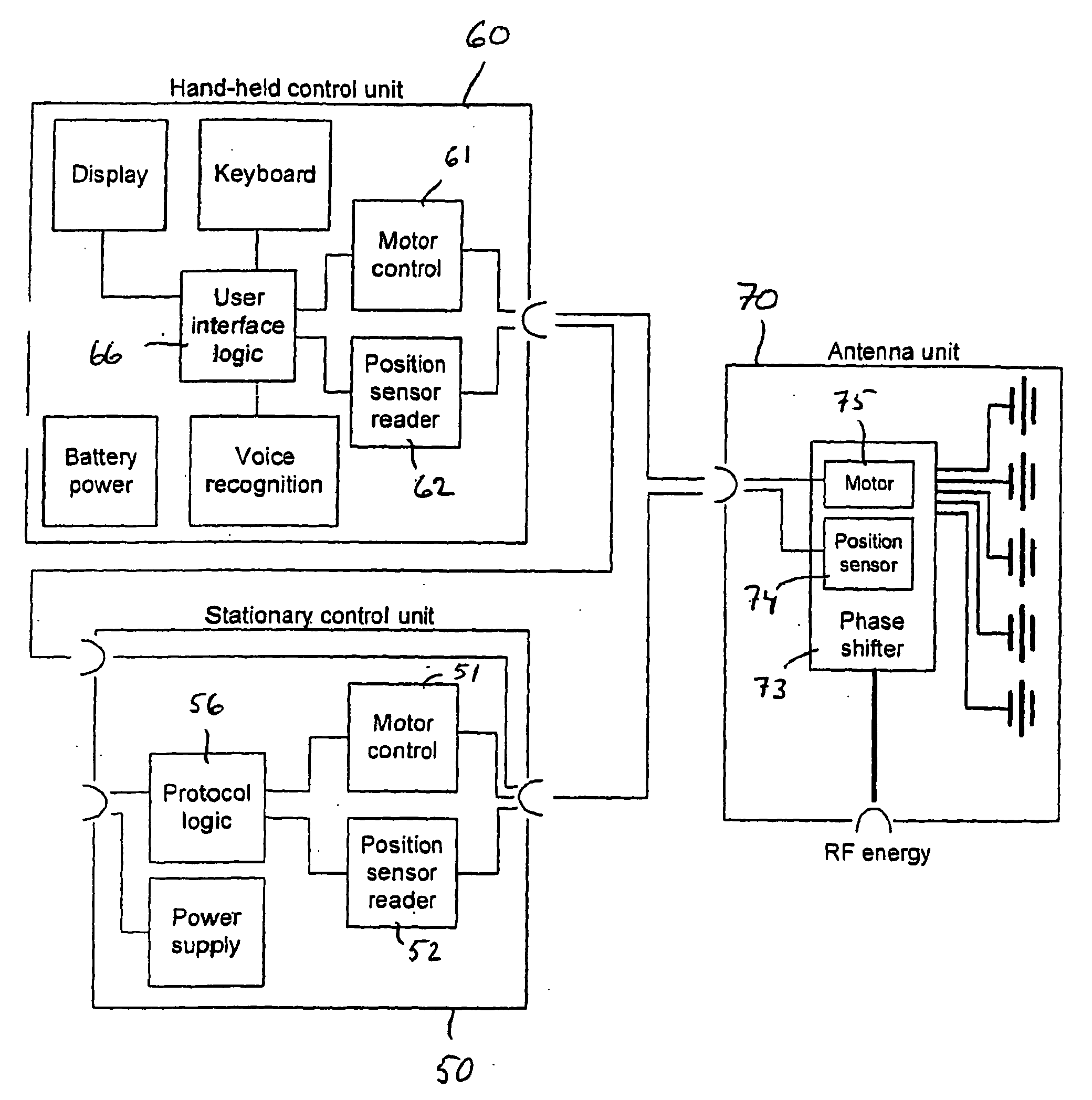
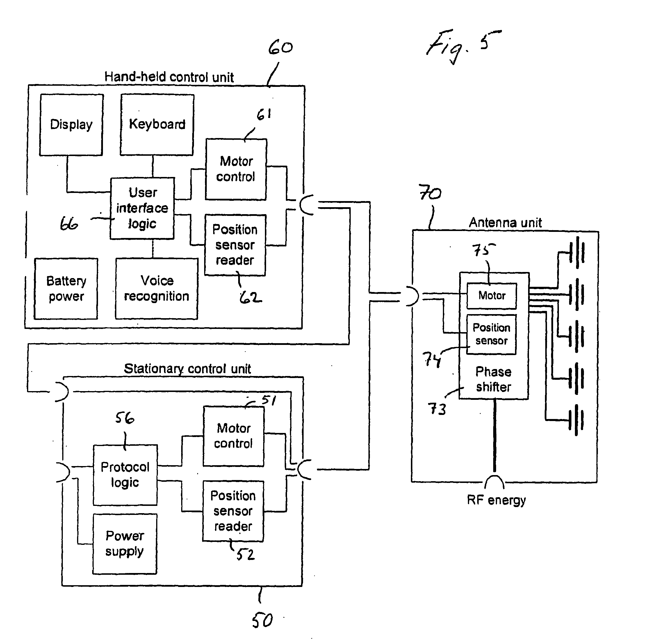
[0026]The external control units 50 and 60 can be used alone or in combination with each other. Each of them contain, as appears from FIGS. 3 and 4, some external components of a control system serving to adjust the electrical tilt of the antenna unit 70. The antenna unit 70 also includes, as is schematically shown in FIG. 2, a number of components forming part of the control system.

[0027]The antenna unit 70 includes a set of antenna elements 71a, 71b, 71c, 71d, 71e being arranged in a vertical column (or in an array including a number of vertical columns arranged side by side). The ante...


PUM


Abstract

An improved control system for controlling the electrical tilt, i.e. the electrically controlled inclination of a radiated beam, of a base station antenna (70) with a vertical row of antenna elements is disclosed. The antenna includes a phase shifting device (73) including a tilt adjusting mechanism with a displaceable mechanical element for adjusting an electrical tilt setting of the antenna lobe being radiated from the antenna. The control system is divided into two parts, namely a first part, including the entire tilt adjusting mechanism (73), an electrical motor (75) and a position sensor (74), these elements constituting internal components being arranged inside the antenna casing (70), and a second part, including the remaining components of the control system, including an electrical motor control circuit (51; 61), and a logic circuit (56; 66) determining the electrical tilt setting. The external components are disposed in a separate, external control unit (50; 60) located outside but in the vicinity of the antenna casing (70), and are adapted for operative coupling, by way of a direct electric wire connection or a capacitive coupling, to the internal components (73,74,75) located inside the antenna casing.

Description

FIELD OF THE INVENTION[0001]The present invention relates to a control system for controlling the electrical tilt, i.e. the electrically controlled inclination of a radiated beam, of an antenna unit, e.g. a base station antenna mounted on a tower or on a frame structure, the antenna unit being provided with a casing accommodating a number of antenna elements, a feeder cable coupled to the antenna elements for feeding RF energy to and from the antenna elements, and a phase shifting device including a tilt adjusting mechanism with a displaceable mechanical element for adjusting an electrical tilt setting of the antenna lobe being radiated from the antenna, said control system comprising an actuating device, including an electric motor for actuating said displaceable mechanical element, and a position sensor for sensing the position of said displaceable mechanical element.[0002]The invention also relates to an antenna system comprising an antenna unit with such a control system.PRIOR A...

Claims


Application Information

Patent Timeline
Patent Type & Authority Applications(United States)
IPC IPC(8): H01Q3/00
CPCH01Q1/246H01Q21/08H01Q3/32H01Q3/005
Inventor AHLBERG, MIKAEL
Owner INTEL CORP
Why Eureka
Try Eureka