Roof mounting system

Active Publication Date: 2012-02-28
LIU JUN
View PDF32 Cites 125 Cited by
  • Summary
  • Abstract
  • Description
  • Claims
  • Application Information

AI Technical Summary

Benefits of technology

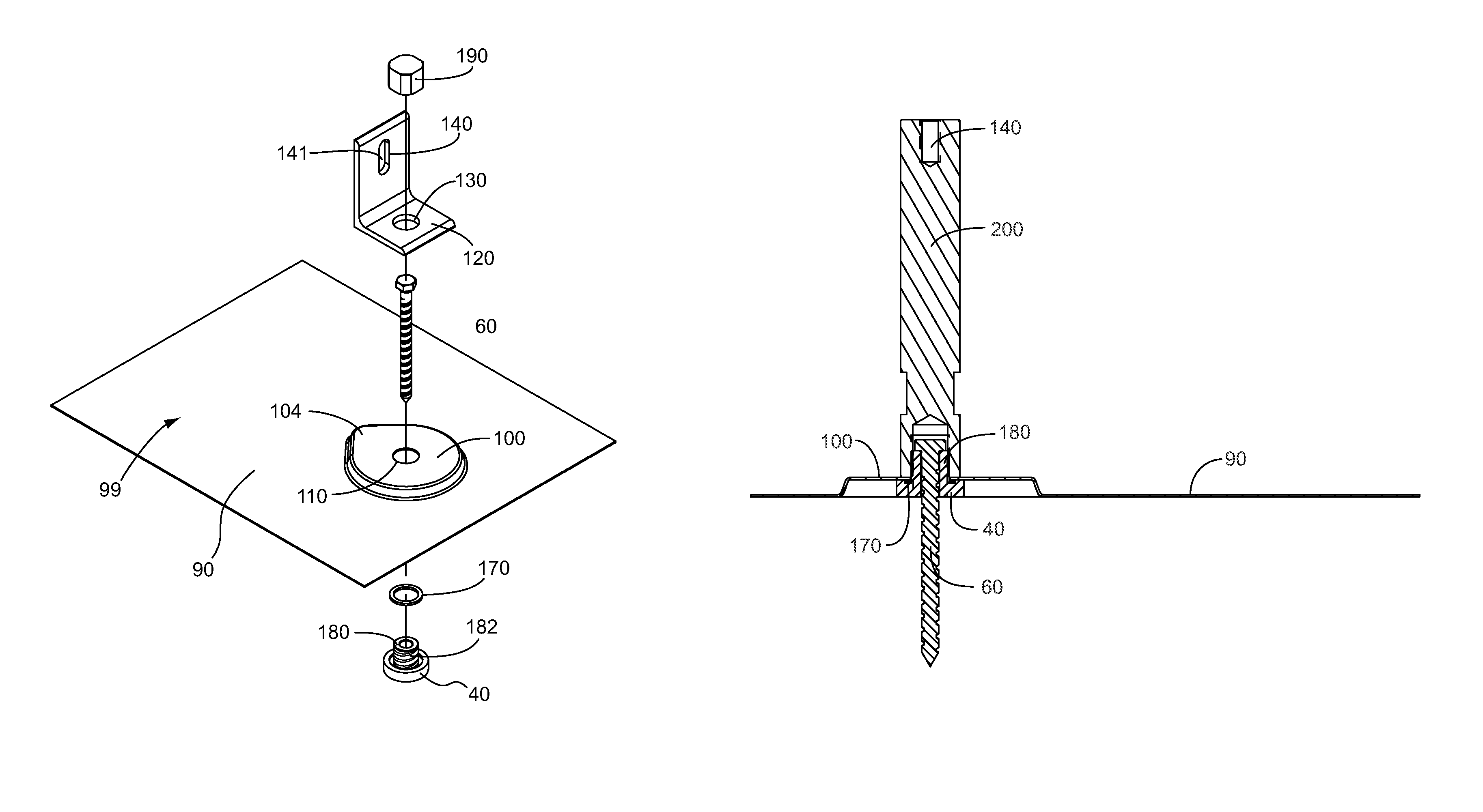
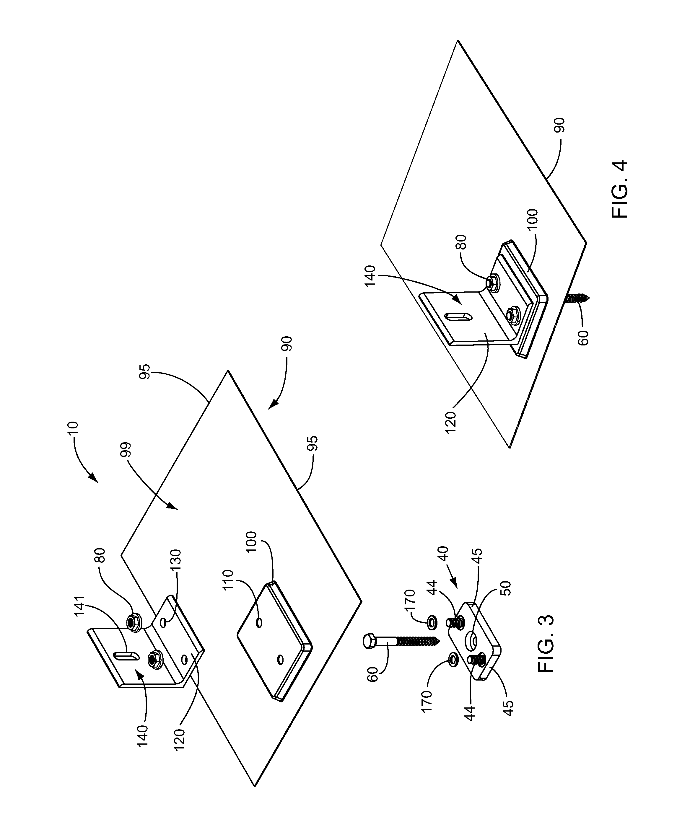
[0010]The following embodiments provide additional advantages and benefits of using fewer parts by integrating structures thereby reducing the costs and steps of installation. In one embodiment, the at least one mounting aperture and the at least one bracket projection are combined into at least one hollow projection whereby the mechanical wood fastener passes through the at least one hollow projection. In another embodiment, the at least one hollow projection is threaded on an outside surface thereof and the mechanical machine fastener is a threaded cap. In another alternate embodiment, the threaded cap and the mounting bracket are combined into an integral mounting cap. In one more embodiment, the base plate and the mechanical wood fastener are combined into an integral base fastener.
[0011]The present invention is a system that allows relatively easy and inexpensive mounting o

Problems solved by technology

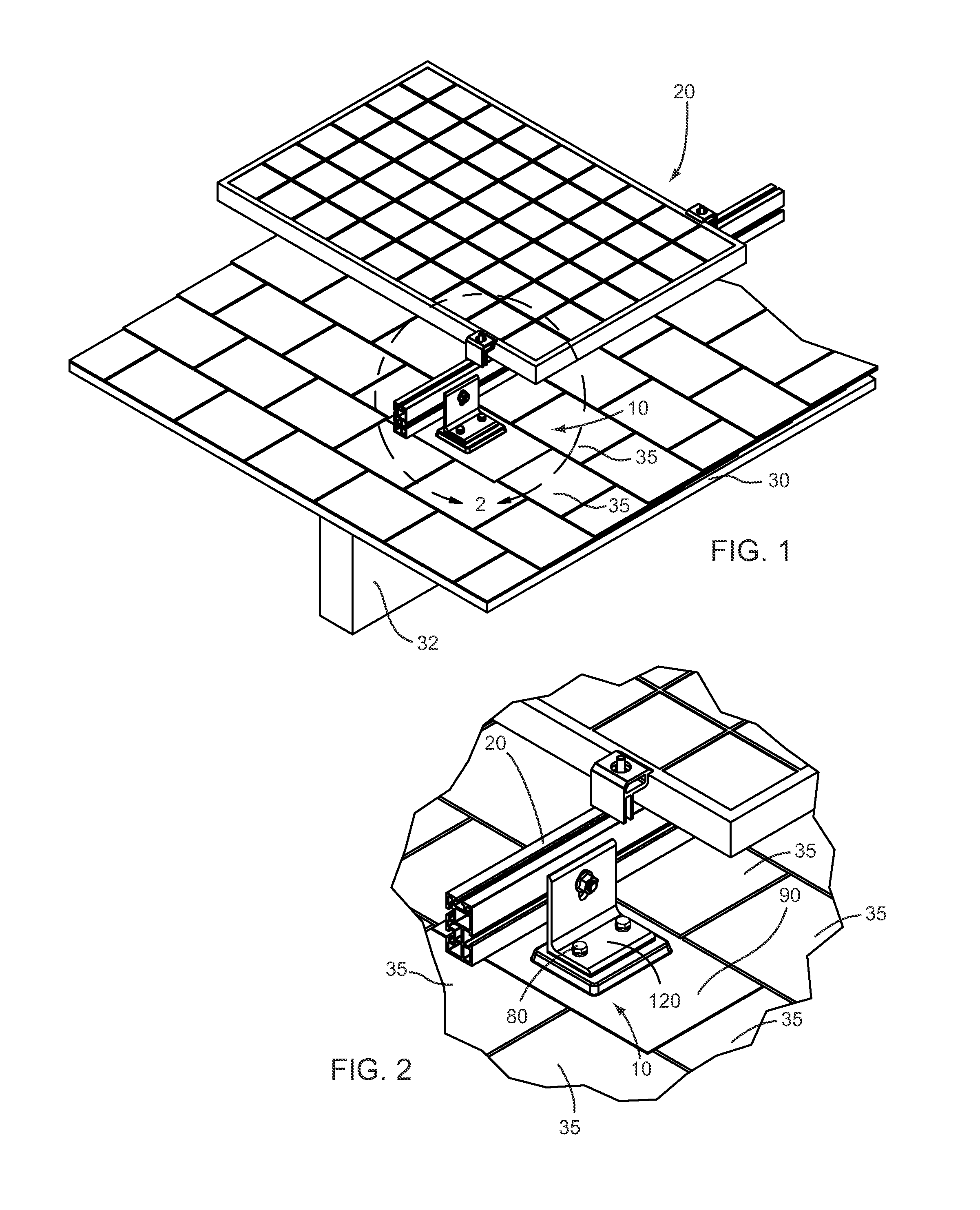
Conventional mounting brackets allow such equipment to be mounted to a roof, but leave pathways for water to flow to the roof, resulting in an increased likelihood of roof leakage.
However, such a device leaves a considerable gap between the flashing plate and the roof, due in part to the thickness of the base pla

Method used


Image

  • Roof mounting system
  • Roof mounting system
  • Roof mounting system

Examples


Example

[0036]Illustrative embodiments of the invention are described below. The following explanation provides specific details for a thorough understanding of and enabling description for these embodiments. One skilled in the art will understand that the invention may be practiced without such details. In other instances, well-known structures and functions have not been shown or described in detail to avoid unnecessarily obscuring the description of the embodiments.

[0037]Unless the context clearly requires otherwise, throughout the description and the claims, the words “comprise,”“comprising,” and the like are to be construed in an inclusive sense as opposed to an exclusive or exhaustive sense; that is to say, in the sense of “including, but not limited to.” Words using the singular or plural number also include the plural or singular number respectively. Additionally, the words “herein,”“above,”“below” and words of similar import, when used in this application, shall refer to this appli...


PUM


Abstract

A system is disclosed for mounting equipment, such as solar panels, to a roof that has shingles. A base plate has at least one mounting aperture therethrough for securing to the roof with a mechanical wood fastener, and at least one bracket projection in an upper surface thereof for securing with a mechanical machine fastener. A flashing plate has a base plate recess formed in a lower surface thereof for receiving the base plate therein. A mounting bracket has at least one aperture therein for receiving one of the bracket projections therethrough for securing the mounting bracket to the at least one bracket projection in the base plate, and through corresponding apertures in the flashing plate. The mounting bracket further includes an attachment aperture adapted to be fixed with the equipment. Additional advantages include using fewer parts by integrating above elements to reduce the costs and steps of installation.

Description

CROSS-REFERENCE TO RELATED APPLICATIONS[0001]This application is a Continuation-in-Part of U.S. patent application Ser. No. 12 / 698,634, filed on Feb. 2, 2010, incorporated herein by reference.STATEMENT REGARDING FEDERALLY SPONSORED RESEARCH AND DEVELOPMENT[0002]Not Applicable.FIELD OF THE INVENTION[0003]This invention relates to solar panel installation hardware, and more particularly to roof-based solar panel installation hardware.DISCUSSION OF RELATED ART[0004]Solar panel installations on residential and business rooftops are become more popular, and consequently there is a need for more effective methods for mounting such equipment to roofs while preventing water from leaking through the roof. Conventional mounting brackets allow such equipment to be mounted to a roof, but leave pathways for water to flow to the roof, resulting in an increased likelihood of roof leakage.[0005]The device disclosed in U.S. Pat. No. 6,526,701 to Stearns et al. on Mar. 4, 2003, teaches a roof mountin...

Claims


Application Information

Patent Timeline
IPC IPC(8): E04D13/18
CPCF24J2/5245F24J2/5247F24J2/5205F24J2002/4667F24J2002/4669F24J2002/5226Y02B10/20Y02E10/47F24S25/33F24S25/61F24S25/613F24S2025/6005F24S2025/6006F24S2025/807
Inventor LIU, JUN
Owner LIU JUN
Why Eureka
Try Eureka