Analog ultrasound beamformer

Active Publication Date: 2017-05-25
ANALOG DEVICES INC
View PDF23 Cites 9 Cited by
  • Summary
  • Abstract
  • Description
  • Claims
  • Application Information

AI Technical Summary

Benefits of technology

[0005]Systems and methods are disclosed herein for using sampled analog technology in an ultrasound system to reduce the power usage of the system and minimize the number of components in the system. In particular, the power

Problems solved by technology

Traditional ultrasound systems have very high power requirements.
In addition, in traditional systems, the beamformer is in the

Method used


Image

  • Analog ultrasound beamformer
  • Analog ultrasound beamformer
  • Analog ultrasound beamformer

Examples


Example

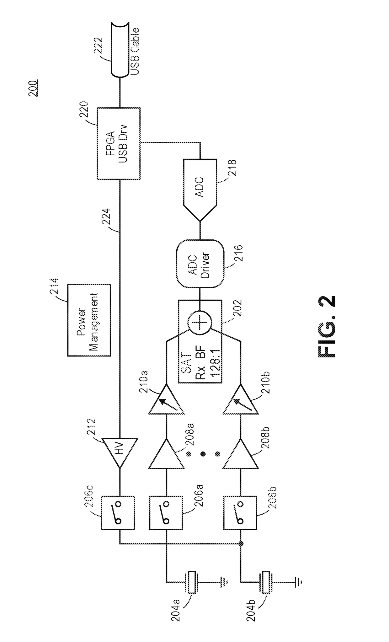
[0035]Systems and methods are disclosed herein for using sampled analog technology in an ultrasound beamformer. Sampled Analog Technology (SAT) refers to systems in which an incoming analog signal is used directly in the system without first being converted to a digital signal. Using sampled analog technology reduces the power usage of the beamformer and reduces the number of components in the system such that the ultrasound beamforming system fits into the ultrasound probe.

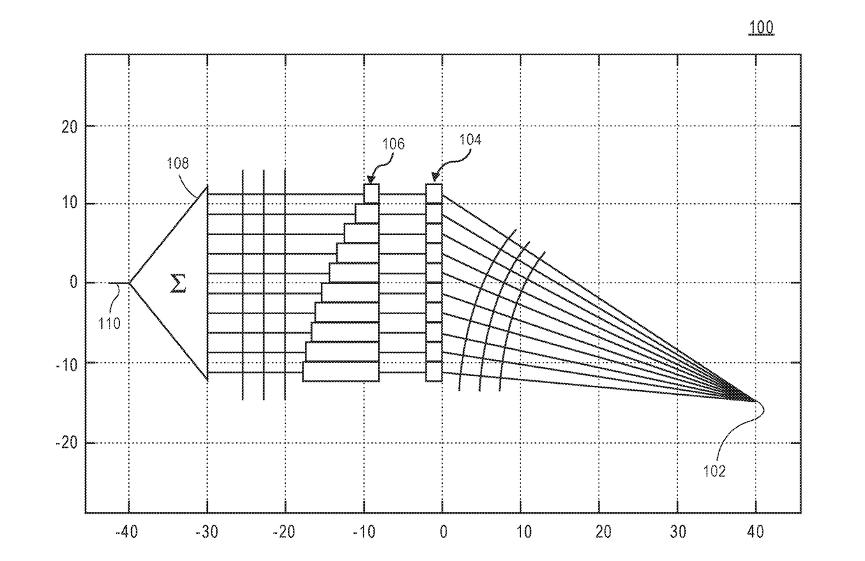
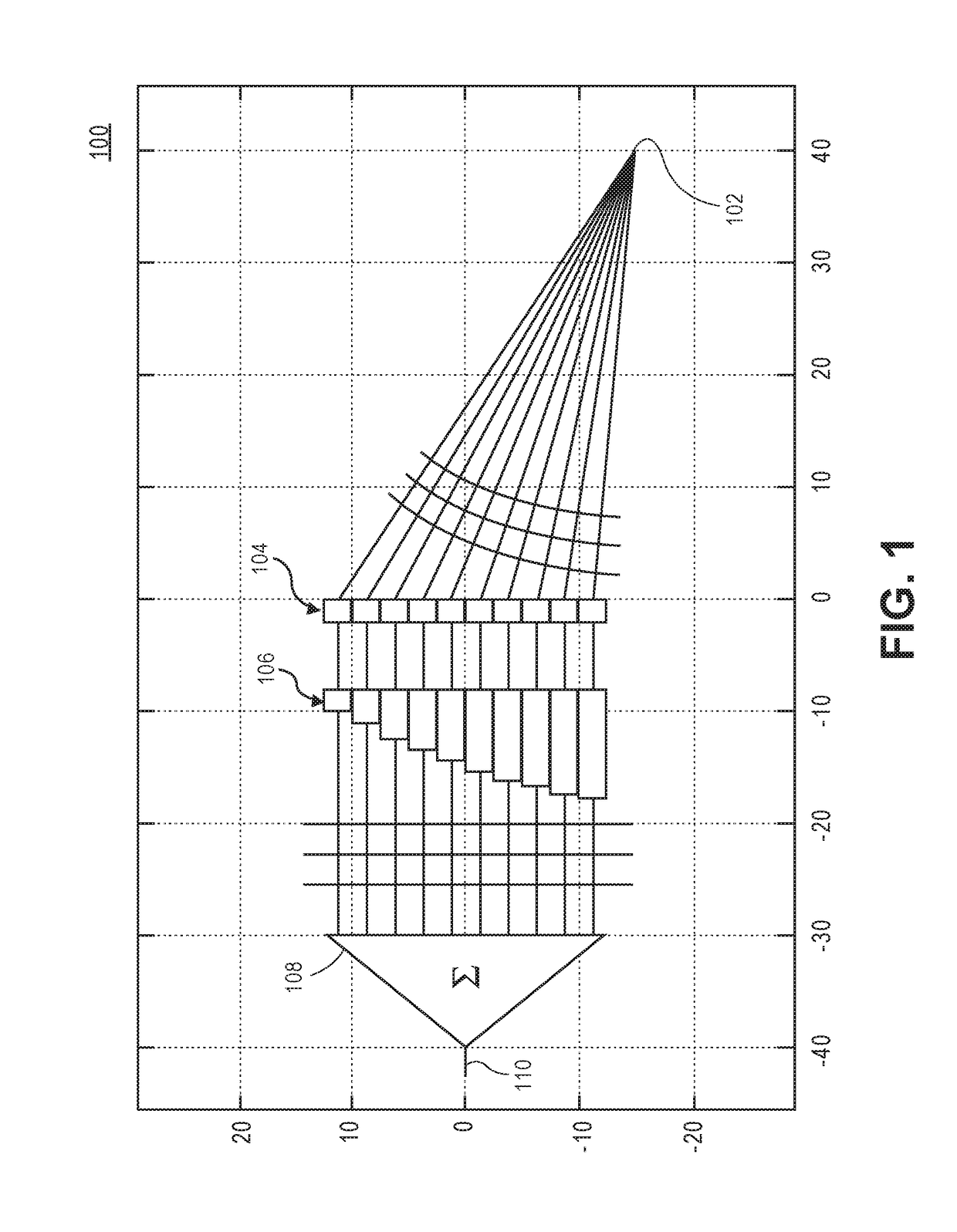
[0036]Ultrasound imaging products use delay-and-sum beamforming to focus transmit and receive pressure waves. Current ultrasound imaging products implement delay-and sum beamforming in the digital domain for performance reasons. However, Sampled Analog Technology (SAT) can perform delay-and-sum beamforming functions in the analog domain, thereby reducing the use of resources such as memory and power. Disclosed herein are systems and methods for a SAT Ultrasound Analog Beamformer (UABF) that uses more than one hun...


PUM


Abstract

A sampled analog beamformer for ultrasound beamforming includes an array of transducers for transmitting analog signals and receiving reflected analog signals, and a sampled analog filter for filtering the received reflected analog. The sampled analog filter includes a delay line for adding a delay to each of the received reflected analog signals. Using a sampled analog filter in an ultrasound beamforming system reduces the power usage of the system and decreases the number of components in the system.

Description

CROSS-REFERENCE TO RELATED APPLICATION[0001]This application claims the benefit of priority under 35 U.S.C. §120 of U.S. Application Ser. No. 62 / 257,706 filed Nov. 19, 2015, and entitled “Analog Ultrasound Beamformer”, naming Eric G. Nestler as inventor. The disclosure of the prior application is considered part of and is incorporated by reference in the disclosure of this application.FIELD OF THE DISCLOSURE[0002]The present invention relates to the field of ultrasound technology, in particular to ultrasound beamformers.BACKGROUND[0003]Ultrasound uses echolocation for detection and imaging. Ultrasound machines utilize arrays of microphones and speakers to perform excitation and recording of echoes from the item being investigated. A signal including ultrasonic energy is transmitted through an ultrasound transducer in short bursts. After each burst, for a short period of time correlating to the amount of time for the ultrasonic energy to reach a target and reflect back to the transdu...

Claims


Application Information

Patent Timeline
IPC IPC(8): G01S7/52A61B8/00A61B8/08A61B8/06
CPCG01S7/52047A61B8/5215A61B8/4483A61B8/06G01S7/524G01S7/526A61B8/5207G01S7/52003G01S7/52095G01S15/8915G01S15/8927G01S15/8997G10K11/346
Inventor NESTLER, ERIC G.
Owner ANALOG DEVICES INC
Why Eureka
Try Eureka