
Display device and method for driving same

Inactive Publication Date: 2015-01-29
SHARP KK
View PDF3 Cites 4 Cited by
  • Summary
  • Abstract
  • Description
  • Claims
  • Application Information

AI Technical Summary

Benefits of technology

The present invention is a display device that can save electricity when writing image signals from outside sources. This reduces the amount of power needed to display information.

Problems solved by technology

That is, the liquid crystal display devices are thin, lightweight, and low in electric power consumption.

Method used


Image

  • Display device and method for driving same
  • Display device and method for driving same
  • Display device and method for driving same

Examples


embodiment 1

[0027]The following description will discuss an embodiment of the present invention with reference to FIGS. 1 through 5.

[0028](Display Device 1)

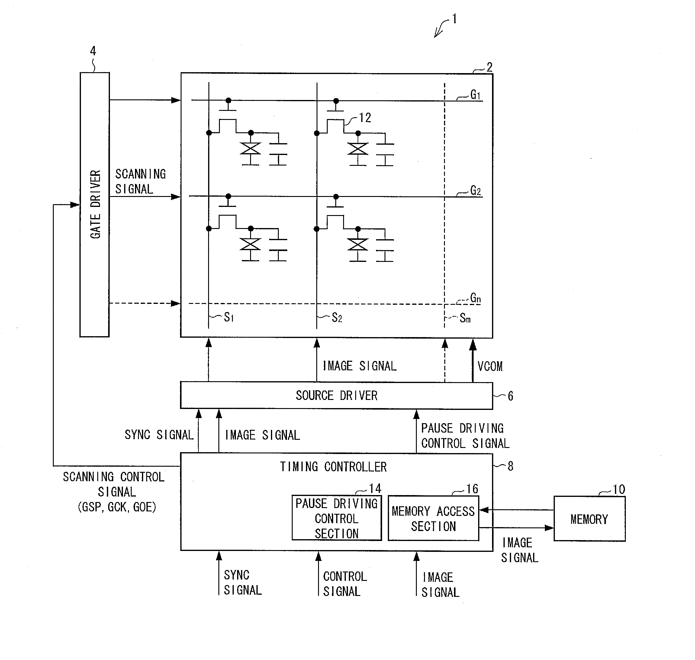
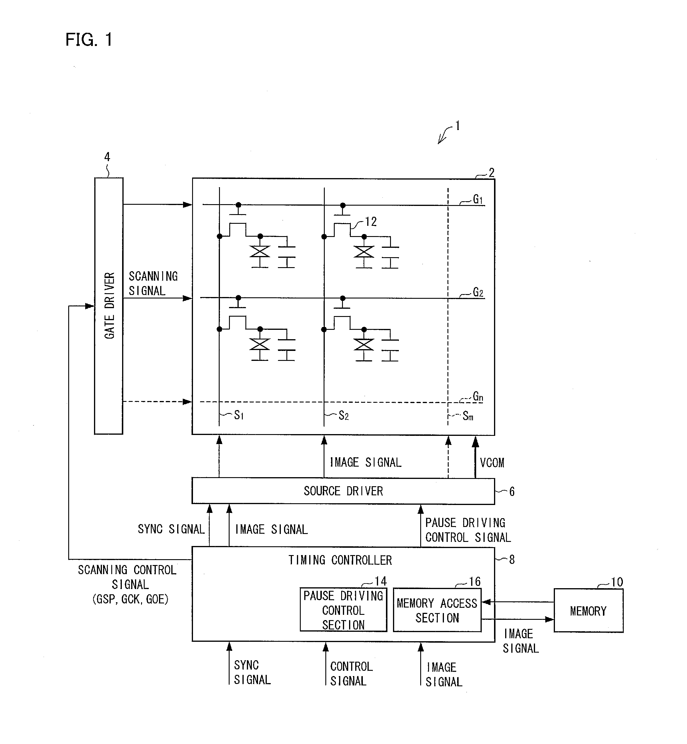
[0029]FIG. 1 is a block diagram illustrating, in detail, a configuration of a display device 1 in accordance with Embodiment 1. As illustrated in FIG. 1, the display device 1 includes a display panel 2, a gate driver 4 (scanning signal output means), a source driver 6 (image signal output means), a timing controller 8, and a memory 10. The timing controller 8 includes a pause driving control section 14 (control signal output means) and a memory access section 16 (writing means, reading means, and receiving means).

[0030]The display panel 2 includes a screen having a plurality of pixels arranged in a matrix manner. The display panel 2 further includes N (N is any integer) scanning lines G (gate lines) which are to be selected sequentially so that the screen is scanned line-sequentially. The display panel 2 also includes M (M is any integer) da...

embodiment 2

[0096]The following description will discuss Embodiment 2 of the present invention with reference to FIGS. 6 through 8. Note that identical reference numbers are given to respective members identical to those in Embodiment 1 and detailed description of the members will be omitted.

[0097]FIG. 6 is a block diagram illustrating a configuration of a main part of a display device 1a in accordance with Embodiment 2 of the present invention. As illustrated in FIG. 6, the display device 1a includes a region control section 18, in addition to the members included in the display device 1 illustrated in FIG. 1. The region control section 18 is provided in a timing controller 8.

[0098]The display device 1a of Embodiment 2 carries out pause driving with respect to a pause region, which is part of a region on a screen of a display panel. Meanwhile, the display device 1a does not carry out pause driving but carries out normal driving with respect to a normal scanning region, which is the other part ...


PUM


Abstract

A memory access section 16 writes, in a memory (10), a received image signal, in a case where a current frame is one that is located right before a frame in a scanning signal. On the other hand, the memory access section 16 does not write, in the memory (10), a received image signal, in a case where the current frame is one that is located right before a frame in a pause period. This allows a further reduction in electric power used to write, in the memory (10), an image signal received from outside.

Description

TECHNICAL FIELD[0001]The present invention relates to (i) a display device which carries out a pause driving and (ii) a method of driving the display device.BACKGROUND ART[0002]Conventionally, liquid crystal display devices have been employed for a wide variety of electronic devices. The liquid crystal display devices have the following advantages. That is, the liquid crystal display devices are thin, lightweight, and low in electric power consumption. Therefore, it is expected that utilization of the liquid crystal display devices will be more increased.[0003]In recent years, a common object of various display devices has been to reduce electric power consumption. As one of effective techniques of attaining this object, pause driving has been suggested. A display device which carries out the pause driving does not scan its display panel in each frame in a subsequent pause period after scanning the display panel in each frame in a scanning period. In the pause period, voltages appli...

Claims


Application Information

Patent Timeline
IPC IPC(8): G09G3/36
CPCG09G3/3674G09G2310/0294G09G2330/023G09G3/3614G09G3/3648G09G2300/0426G09G2300/0876G09G2330/021
Inventor KOBAYASHI, FUMIYUKIFUJIOKA, AKIZUMIYAMATO, ASAHINAKANO, TAKETOSHIYANAGI, TOSHIHIRO
Owner SHARP KK
Learn More