

Method and Apparatus for Controlling Light Levels to Save Energy
- Summary
- Abstract
- Description
- Claims
- Application Information
AI Technical Summary
Benefits of technology
Problems solved by technology
Method used
Image

Examples
Embodiment Construction
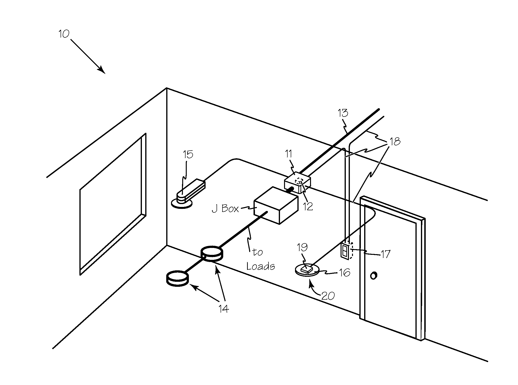
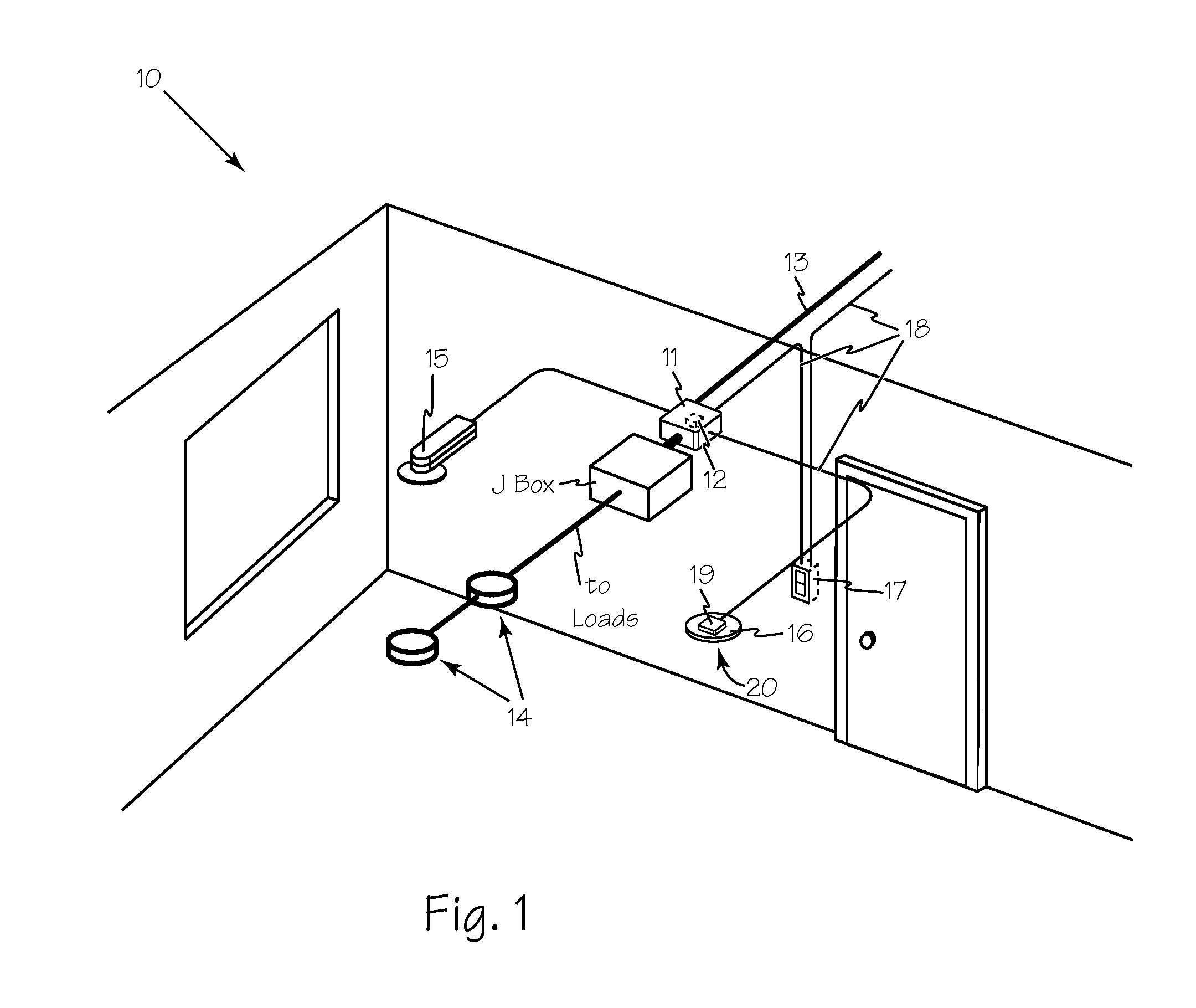
[0015]FIG. 1 illustrates lighting system 10 for controlling light levels to save energy. System components are connected together via any suitable cables that carry a communication bus and low voltage power connections such as Wattstopper's Lighting Management Registered Jack (LMRJ) cables or any other suitable network cables such as CAT5 network cables. A Room Controller 11, such as the LMRC-102 includes internal microcontroller 12 and essential and nonessential circuits is connected to mains power 13 to generate low voltage power for the system and is also the control component that controls power to the lighting load 14 (on / off relay control for two independent lighting loads for this model). Other system components include closed loop daylight sensor 15 (an LMLS-400), a dual technology occupancy sensor 16 (LMDC-100 using ultrasonic and pyroelectric infrared sensors), and a suitable light switch 17 such as an LMSW-102 two position wall switch. An ambient light threshold is set us...
PUM
 Abstract
Description
Claims
Application Information