Projector type vehicle light

Inactive Publication Date: 2005-06-30
ICHIKOH IND LTD
View PDF2 Cites 9 Cited by
  • Summary
  • Abstract
  • Description
  • Claims
  • Application Information

AI Technical Summary

Benefits of technology

[0015] It is hence an object of the present invention to provide a projector type vehicle light which is minimized in the number of components as well as the overall weight, stabilized in the direction of light, improved in the intensity

Problems solved by technology

However, the vehicle light 100 has a disadvantage that while the light source bulb 2 releases an output of light at higher thermal energy, the convex lens 3 has to be made of a glass material thus increasing the overall weight.
Also, the assembly process may however be troublesome in which the light axis to be set at higher precision is deviated from the des

Method used


Image

  • Projector type vehicle light
  • Projector type vehicle light
  • Projector type vehicle light

Examples


Example

[0082] Referring now to FIGS. 13A˜16D, a second to a fourth embodiments according to the present invention will be described hereinbelow.

[0083]FIGS. 13A to 13C illustrate the small projector type lamp 10B according to the second embodiments.

[0084] In action, the LED 11 in the small projector type lamp 10B can be tilted and inclined backward about (around) F1. In other words, a light emitting potion of the LED is inclined so as to be lowered in the backward direction of the small concave mirror 7, as shown in FIG. 13B. The tilting movement may be set to an angular range of θ1.

[0085] When the LED 11 of the small projector lamp 10B is tilted through the backward movement θ1 as shown in FIG. 13B, it projects the pattern of lighting LP1 having the spot S (See FIG. 18A).

[0086]FIGS. 14A to 14D illustrate a small projector type lamp 10C which is multi-functioned for modifying the pattern of light and used in a vehicle light C of the third embodiment.

Example

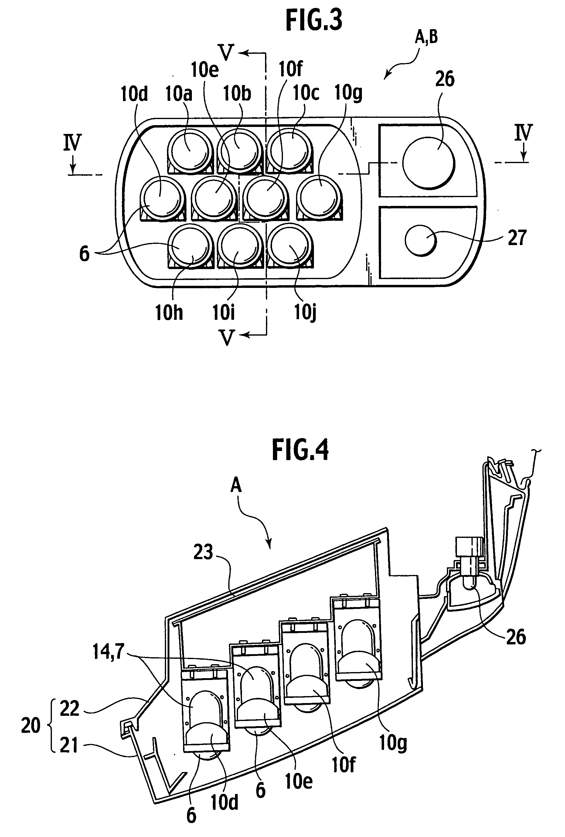
[0087] The vehicle light C of the third embodiment is featured in which at least one of the small projector type lamps 10a to 10j (FIG. 3) is replaced by a small projector type lamp 10C while the others are constructed in the fundamental structure of the small projector type lamp 10. The small projector type lamp 10C is designed with the LED 11 arranged tiltable about the optical axis Z so as to be set with an angle θ2 as shown in FIG. 14D.

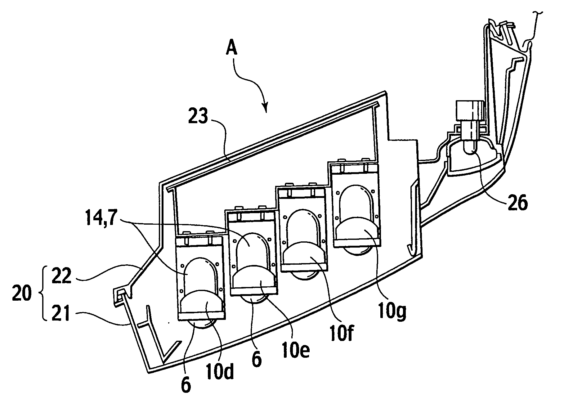
[0088] As the small projector type lamp 10C is designed for multi-function, it replaces at least one of the small projector type lamps 10a to 10j in the vehicle light A (See FIG. 3).

[0089] The small projector type lamp 10C is designed with the LED 11 arranged tiltable about the optical axis Z thereof for moving the spot S (denoted by the hatching in FIG. 15) in the pattern of lighting LP to the left and the right as denoted by the arrows in FIG. 15, namely, the hot zone LP2 is offset and shifted leftward from the previous hot zone LP1 in a direc...

Example

[0092] The vehicle light B of the fourth embodiment is featured in which at least one of the small projector type lamps 10a to 10j (FIG. 3) is replaced by a small projector type lamp 10D while the others are constructed in the fundamental structure of the small projector type lamp 10. The small projector type lamp 10D is offset in a leftward or rightward direction of an orthogonal axis Z1 extending at a right angle to the optical axis Z of the small projective type lamp 10D.

[0093] Therefore, the maximum lighting degree of the pattern of lighting LP shown in FIGS. 8aA to 8F can be shifted with 1.5 degrees in the leftward or the rightward so that the small projector type lamp 10D is improved in the intensity of light emitting through the hot zone of a desired pattern with the reflectivity of its concave mirror increased to maximum, especially be useful for varying a load to keep right end or a load to keep left end.

[0094] Referring now to FIGS. 17A˜20, still other embodiments of the...


PUM


Abstract

A projector type vehicle light includes: a light source provided close to the primary focusing point of a concave mirror; and a convex lens, wherein the light source comprises a group of LEDs; each of the LED is located in each of a small concave mirror in a small reflector which has an ellipsoidal surface of rotation or a free surface as a part of the ellipsoidal surface of rotation provided on the inner surface thereof; the convex lens comprises a group of small convex lenses provided to cover the front opening of the small reflectors respectively; each of the LED is located close to the primary focusing point of a small concave mirror in a small reflector and faces at its emitter side to the small concave mirror; and a shade comes close to the secondary focusing point of the small concave mirror and assembled together with the small convex lens and the LED, whereby each of the small projector type lamps in the array is completed.

Description

BACKGROUND OF THE INVENTION [0001] 1. Field of the Invention [0002] The present invention relates to a projector type vehicle light employing an LED (light emitting diode) as the light source for use as a headlamp in a vehicle. [0003] 2. Description of the Related Art [0004]FIG. 1 shows a conventional projector type vehicle light 100 which is disclosed in Japanese Utility model Application Laid-Open No. Hei-6-41010 (Application No. Hei-4-76322). The vehicle light 100 comprises a light source bulb 2 provided close to the primary focusing point of a concave mirror 1 and a convex lens 3 for modulating the flux of light emitted from the light source bulb 2 and reflected by the concave mirror 1 to substantially a parallel light which is then directed towards the front. [0005] More specifically, the vehicle light 100 has a shade 4 provided between the light source bulb 2 and the convex lens 3 for projecting a desired cut-line pattern of light selectively used when the vehicle passes throu...

Claims


Application Information

Patent Timeline
IPC IPC(8): B60Q1/12F21S8/10F21V5/04
CPCB60Q1/12F21S48/1159F21Y2101/02F21W2101/10F21V5/04F21Y2115/10F21S41/147F21S41/148F21S41/153F21W2102/19F21W2102/00
Inventor TAKEDA, YUKARIIWASAKI, KAZUNORISUZUKI, YASUFUMI
Owner ICHIKOH IND LTD
Why Eureka
Try Eureka